Everyone is an inventor and especially you!!
Alternating voltage
With an alternating voltage, each pole is alternately plus and minus. The electrons therefore run back and forth as the forces repelling and attracting them change sides.

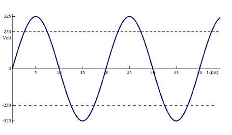
Although alternating voltage can take various forms, it is often sinusoidal, as depicted in the above image. The number of changes per second is expressed as the frequency, f, measured in the unit of Hz.
Because alternating voltage is constantly changing, it is important to know exactly what the alternating voltage is doing at any given moment during measurements. We call this specific moment the phase. The phase is spans 360 degrees before the wave cycle repeats. Notably, the voltage across the poles is exactly 0V at 0, 180 and 360 degrees, while the voltage is at its maximum at 90 and 270 degrees. The distance between 0 and 360 degrees is exactly 1 wavelength, with λ as the symbol and meters as the unit of measurement. The highest voltage is called the amplitude, and the difference between the negative and positive amplitudes is called the peak-to-peak voltage or top/top voltage. The other units and values for alternating current are the same as those for direct voltage. Voltage is represented by the symbol U and the unit Volt. Current has the symbol I, and the unit A. As an example, in Europe, 230V AC at 50 Hz is supplied via the socket (AC stands for alternating current).
The effective value
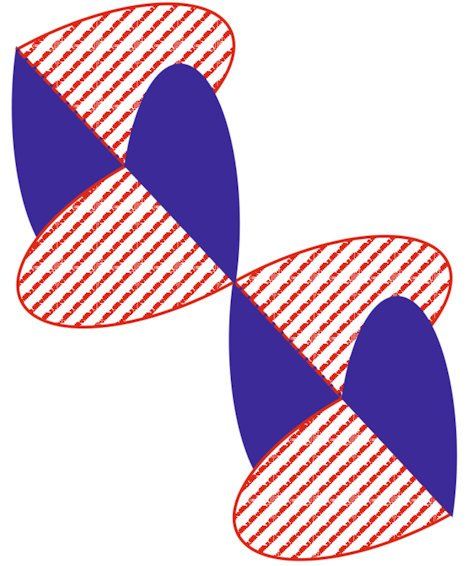
The amplitude of an alternating voltage can be either positive or negative. This basically means that an alternating voltage is usually smaller than its amplitude. Let's suppose we connect an AC voltage with an amplitude of 10 V to a 1 ohm resistor. Given that power is P = U * I, the power should be 10 watts. In reality, though, this isn't quite right. Ultimately, the voltage is only equal to the amplitude for a brief period of time. For the majority of the time, the voltage is actually lower than the amplitude, which means the power is also lower. The graph of power follows the graph of voltage! A DC voltage of 10 V on a 1 ohm resistor produces 10 Watts continuously. This means that an alternating voltage with an amplitude of 10 V delivers much less power than a direct voltage of 10 V. You can see this in the following illustration.
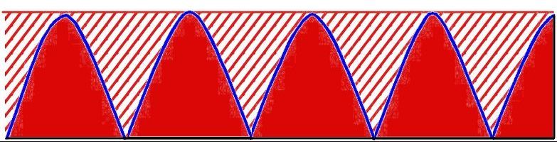
The shaded part shows the power delivered by the DC voltage, and the red wave shows the power delivered by the AC voltage. The negative phase also delivers power, so it's visible as a positive wave. To deliver the same power as a given DC voltage, we need an alternating voltage with a higher peak-to-peak voltage. That is why, when we discuss AC voltage, we usually talk about the effective value of that alternating voltage (and current). The effective value of an alternating current is the value of the direct voltage that supplies the same power as the alternating voltage. See the formula: Veff = VAC/√2. The peak-to-peak voltage is therefore much higher than the effective voltage. For example, the peak-to-peak voltage of our 230 VAC (effective) is no less than ±325 V.
Alternating voltage has the advantage that it can be used for inductive transfer (see our section on coils and transformers). This makes it easy to transform alternating voltage into other voltages. And that is essential for the transport of energy (see the section on cable losses).
Using alternating current, we can also create electromagnetic waves. These travel at the speed of light through space and air, among other things, and are the basis of (almost) all wireless data transfer, such as Wi-Fi.
The propagation speed of an alternating current in a substance (such as iron or copper) has the symbol V (velocity) and the unit of meters per second.
You can find the wavelength λ by dividing the propagation speed V by the number of vibrations per second f:
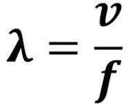
Since the speed of propagation through different substances is different, the wavelength will change if the vibration moves through another substance. This also applies to electromagnetic waves.
Analogue
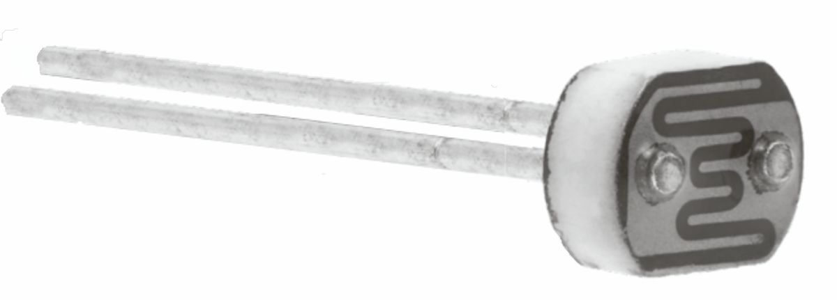
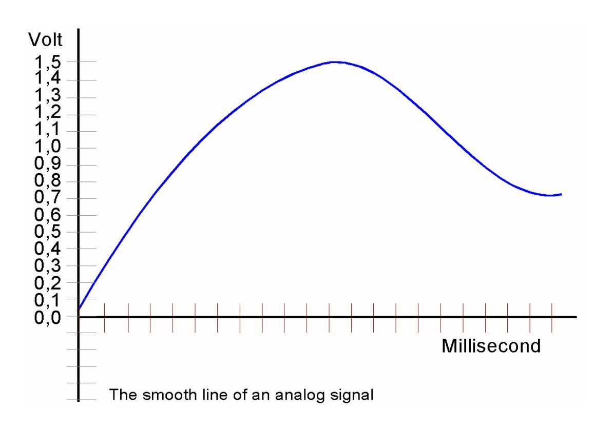
Everything in nature is analogue. A sound can get louder or softer without hearing “steps” between each change. The value changes smoothly. The same is true with light intensity and colour. So, when we translate natural phenomena such as light, sound, colour and movement, into electrical signals with the help of a sensor, we call these analogue signals. The picture shows an analogue signal that, in this case, takes on any value between 0 V and 1.5 V. Most electronics components can handle analogue signals just fine. But there are important parts that know only digital signals. See the section on digital.
Atomic model
An atom is the smallest building block that still has the properties of the material made with that building block. For example, iron consists of iron atoms. If you break things down any further, you end up with particles that are the building blocks of atoms itself like neutrons, protons and electrons.
Atoms often occur in combinations, which we call molecules. The vast majority of materials consist of molecules. Since we cannot see an atom, we try to imagine as best we can what it might look like and how it is put together. Therefore, we make a model, a simplified representation of reality. Just like you can make a drawing of a house, for example; it is not really your house, but it gives an idea of what a house is like.
In our model, the atom consists for the most part out of… NOTHING! In the centre is a nucleus with small positive (protons) and neutral (neutrons) particles. Around it, at a very large fixed distance, a kind of spherical cloud with one or more concentrations of a very small amount of negative energy: electrons. All the particles within the atom are represented in the model as tiny spheres.
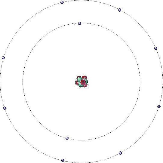
To have an idea of the vast emptiness that exists inside an atom: If the nucleus is a soccer ball on top of Big Ben in London, the first electron is the tip of a needle on the control tower of Heathrow airport, about 18 kilometres away! And yet an atom itself is unimaginably small. There are more atoms in a glass of water than stars in the Milky Way! The electrons in the cloud orbit the nucleus and their charge is exactly balanced with the charge of the nucleus. Therefore, if the nucleus gets larger, more electrons must also move around it to maintain equilibrium. However, the first cloud is "full" with two electrons. If the atom needs more electrons, it uses a second cloud for that purpose at a larger fixed distance in which a maximum of 8 electrons can fit. When that "cloud" is full, the next electrons must again keep a greater distance and so on. Because the clouds are at a fixed distance, they are called shells.
The properties of an atom are mainly determined by the charge of the nucleus and the number of electrons floating around it, precisely the electrons in the outer shell. The composition of atoms is mapped out in the periodic table of elements that you may be familiar with from physics and chemistry. As you might imagine, the bond between an electron and the nucleus gets weaker and weaker as the distance increases. Very large atoms are therefore often unstable and can only exist for a short time before falling apart. 118 electrons seems to be about the maximum.
Ions
Due to strong forces of attraction, an atom can lose electrons to - or gain them from - another atom. When an atom loses or gains an electron, we call the result an ion. Because ions have a charge, they play an important role in electronics, and also in chemistry.
Battery
A battery is an electron pump. A chemical process inside the battery creates a voltage difference at the poles (terminals) that we can use as an energy source. When the supply of chemicals in the battery is exhausted, we call the battery empty. A regular battery then ends up in landfill or is (partially) recycled.
With rechargeable batteries, you can reverse the discharge process by putting electrons back in. That's called recharging. Unfortunately, this does not go on indefinitely, and the battery will be exhausted after 10 to 100 charges. Batteries are very convenient to use. Almost everything now has become cordless, like your cell phone, the drill, your headphones. And with a car, of course, a cord would really be impossible. But there is also a downside; batteries use rare resources that are often extracted from the ground at the expense of local populations. And the enormous use of batteries and the dumping of the resulting waste puts a huge burden on the environment. So, use mains power where it’s possible, and if batteries are really necessary, opt for rechargeable batteries.
Capacitor
A capacitor is a component that blocks direct current and transmits alternating current. A capacitor can also be used to store (a small amount of) energy.
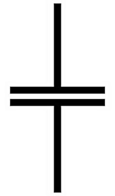
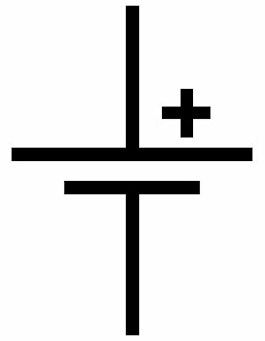
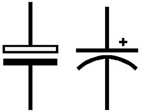
symbol
capacitor

A capacitor consists of two conducting plates with a very thin insulation layer between them. If you now send electrons to one of the plates (we'll call it plate A for now), it will get a negative charge. Because the plates are so close together, the electrons in the other plate (plate B) are pushed away. It seems as if the current passes through the capacitor for a moment, but when the plate is completely full of electrons, the movement stops. If you then remove all the electrons from plate A, it becomes positively charged and the electrons are attracted to plate B. Again it seems as if the electrons are moving through the capacitor, but they are not.
It is only the charging and discharging of plate A that causes the (opposite) discharging and charging of plate B. Plate B therefore always takes on the opposite charge of plate A. And the same is true in reverse, a capacitor has no polarity (plus and minus pole). The larger the plates, the more charge fits on them. The size of the plates and therefore the amount of charge that can fit on them is called the capacity. The unit of capacitance is called Farad. Most capacitors we use are much smaller than 1 Farad. You will encounter values from a few picofarads (pF) to several thousand microfarads (µf). (See the topic on Multiplication factor)
As you can imagine, capacitors with small capacitances fill up quickly. Thus, they can only transmit very fast changes. The larger the capacitance the larger the wavelength that can be transmitted. The other way around: the smaller the capacitance the higher frequency can pass through. The insulator between the plates is very thin. If the voltage gets too high, the insulator will break down and a short circuit will occur between the plates. This is why a capacitor always specifies the maximum voltage.
Bucket capacitor
There are special bucket capacitors that are used to store many more electrons. Officially, they are called “electrolytic capacitors”. These capacitors are polar, though, which means they have a plus pole and a minus pole. Connecting them in reverse breaks the electrolytic capacitor (electrolytic), sometimes with a big bang and a lot of fumes.
Be careful, those fumes are quite toxic! You can use an electrolytic capacitor as a supply bucket for electrons. When you have more than enough, you fill the bucket. As soon as you run short of electrons, you drain the bucket. To show that a bucket capacitor is an electrolytic capacitor, it has a different symbol and a plus and a minus sign on it. The open bar of the symbol is the plus pole of the capacitor. The English/American symbol, which is next to it, is also still widely used.
Water model of the capacitor
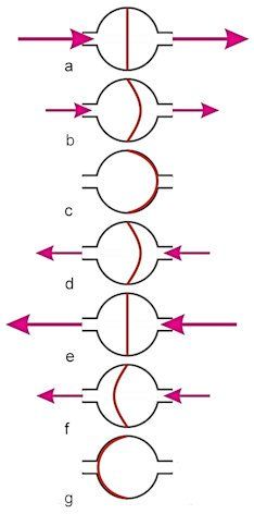
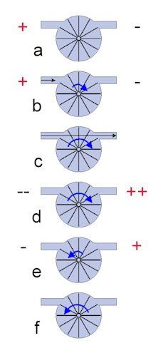
How a capacitor works is easily explained with the help of a water model:
In this, a capacitor is a vessel with a sheet of rubber in the middle. At rest, the sheet hangs in the centre of the vessel.
a) If we apply pressure, the sheet will immediately stretch with it. A lot of current flows, but the voltage across the capacitor is virtually 0!
b) The further the sheet is stretched, the more resistance it will create.
c) Eventually it reaches the final position and increasing the pressure no longer produces any movement. There is now full voltage, but no current flows!
d) If we now remove the water pressure, the rubber sheet will spring back and thus apply pressure itself for a short time! So ther is a current flowing very briefly when we remove the voltage.
e) If we reverse the water pressure, the pressure of the sheet will come on top of the water pressure.
f) The movement now repeats itself in the other direction.
In this way, an alternating current movement can be transmitted through a capacitor.
The voltage and current behavior of a capacitor in detail.
Now let's see, with the help of Ohm's law, what exactly the capacitor does.
When I apply voltage to a capacitor, it first behaves like a short circuit. The resistance at that moment is almost 0 Ω! So a very large current is already flowing, while the voltage is still almost 0 V. Something like this: U = I x R, R = 0.01 Ω. If I = 10 A then the voltage will only be 0.1 V! Now as the rubber sheet is stretched further and further, it holds back the current more and more, in other words: the resistance of the capacitor becomes larger and larger and even almost infinite when the rubber is completely against the output. The resistance is then very large and the current is very small. Something like this: U = I x R, I = 0.00001 A and the resistance = 100000 Ω, then U is 10 Volts. That is peculiar, first the current reaches maximum at zero volts and then the voltage becomes high, while almost no current is flowing. With DC voltage it ends here, the voltage remains high and the resistance is virtually infinite, the current is therefore practically 0.
This is very different with an alternating voltage! This is because the voltage keeps changing, so the capacitor keeps repeating the pattern. You see that the current flows first and then the voltage appears. We call this lag: With an alternating voltage, the voltage across a capacitor lags 90° behind the current!
AC resistance of a capacitor
A capacitor does not pass direct current, but it does pass alternating current. The degree to which the capacitor thereby hinders the alternating current being transmitted is called impedance with the symbol XC. Impedance thus corresponds to alternating current resistance and therefore has ohms as its unit. The AC resistance of a capacitor is calculated as follows:
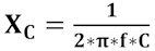
Wherein f is the frequency of the alternating current in Hertz and C is the capacitance of the capacitor in Farad. And, if you don't already know; π is the Greek letter pi and it stands for the number 3.14. To find the AC resistance, first multiply the capacitance by the frequency. Then you multiply that number by 6.28 (2x3.14). Finally, you divide 1 by the result of that sum. The alternating current resistance therefore depends on the frequency! The higher the frequency, the lower the alternating current resistance of a capacitor. A capacitor indeed transmits high frequencies more easily than low frequencies and you will see in circuits that we can make good use of this.
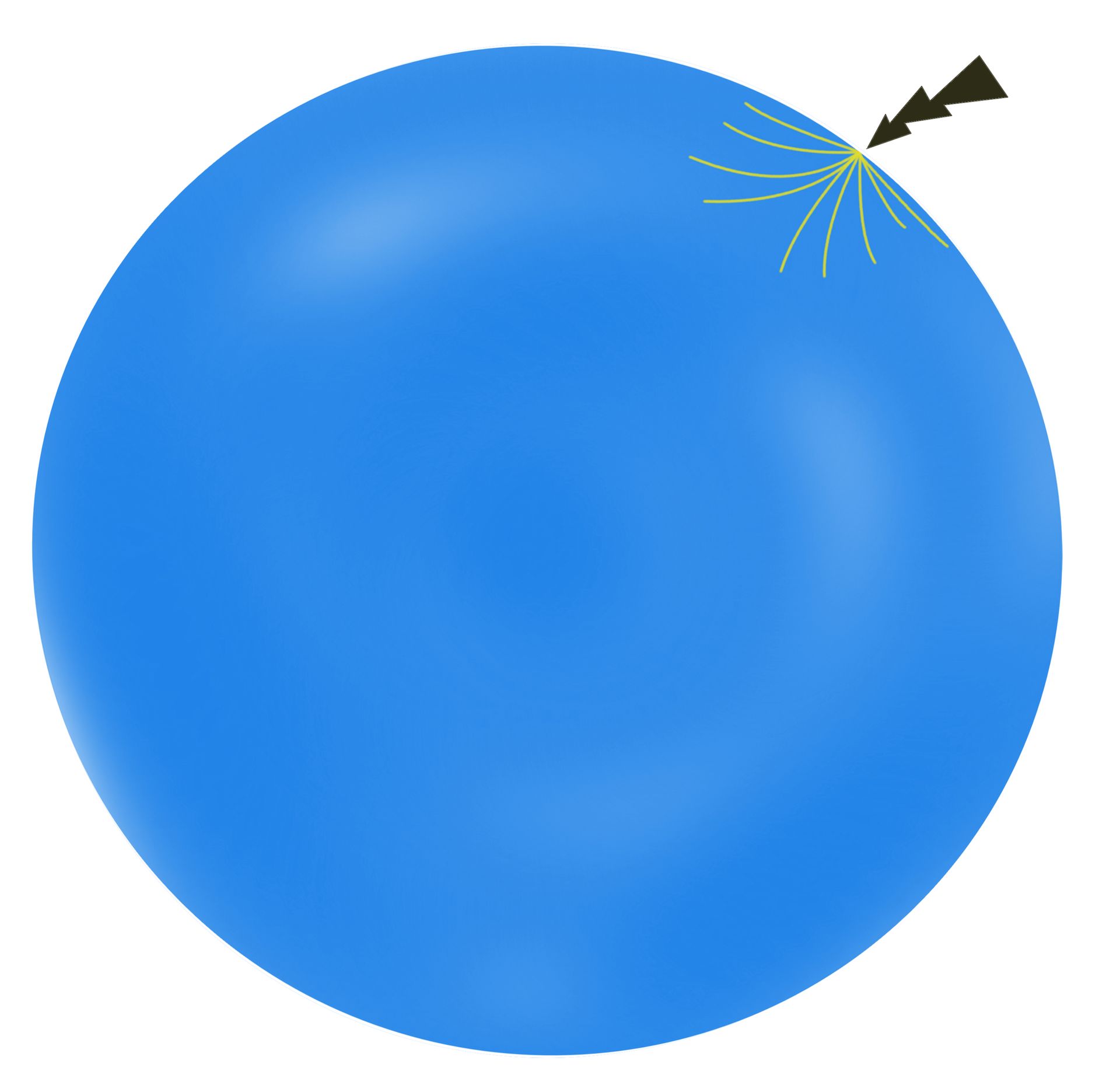
Energy storage/DC behavior of a capacitor
If you charge a capacitor and then put it away, the voltage stays in it, just like in a blown-up balloon. We used to play pranks on one another because of this, by charging a capacitor (that was suitable for it) with a high voltage and then putting it back in the cupboard. The next person who grabbed the capacitor and connected it would get quite a few sparks, to his or her horror! The energy you can store in a capacitor is equal to:
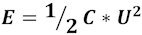
Wherein E is the stored energy, C is the capacitance of the capacitor and U is the voltage. To charge a capacitor you always need a limiting resistor, as an uncharged capacitor has a very low resistance, if not a short circuit. The enormous 'starting current' could destroy the power supply and the capacitor. Therefore, a small series resistance R is included in the circuit.
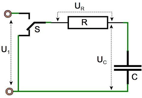
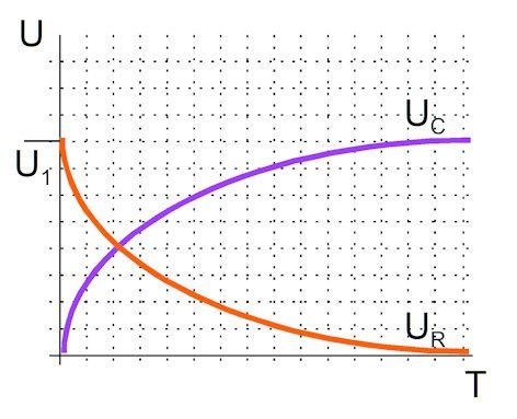
As soon as we flip switch S to U1, the capacitor begins to charge. At t = 0, the capacitor is a short circuit and all voltage falls across the resistor R. Maximum current flows through the resistor R (I = U1/R). The capacitor begins to charge and thus the resistance of the capacitor increases. Charging occurs according to an exponential function: the resistance of C keeps increasing, which makes charging slower and slower. After charging time: R*C (Ω and farad), the capacitor is 63% charged. After 5*R*C, the capacitor is fully charged and no more current flows. The voltage U1 is now completely across the capacitor C. If we now reset the switch to 0 V, exactly the opposite will happen. The capacitor will discharge through the resistor R according to an exponential function. The fully charged capacitor carries the voltage U1 and causes a large current in the resistor. The more the voltage drops, the smaller the current through the resistor and after the discharge time 5*R*C the capacitor is completely discharged.
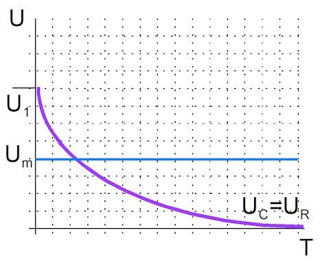
When using a capacitor as an energy storage, you must take into account the lowest voltage Um at which your connected circuit is still operating. The discharge curve of the capacitor and the minimum working voltage. From the graph you can see that only a small part of the capacity can be used as a result. After that, the voltage already drops below the minimum working voltage Um. Therefore, in this type of situation, a switching power supply is often used that can raise a low voltage. You will find examples of this in the example circuits shown in the book: circuit 12 and circuit 13.
Applications: Capacitors are widely used in filters because the alternating current resistance depends on the frequency. You also use capacitors if you only want to transmit alternating current signals, the so-called coupling capacitors.
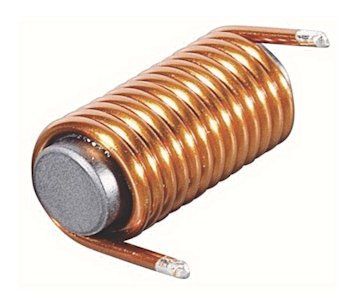
Coil
A coil is essentially composed of a conducting wire, wrapped around a central core, which may or may not include an iron insert. To understand a coil, we have to go back to physics class. We know from there that when you have a wire with a flowing current, a magnetic field is created around it (see “Spooky business” in letter 14).
By winding the wire around a core, the windings amplify each other’s magnetic field in such a way that the coil generates a magnetic north pole at one end and, of course, the south pole at the other end. Which side the poles end up on will depend on the direction of current flow.
Coils come in many shapes and sizes, and with different core materials, but the basic principle of the coil is always the same.
A coil always works against (resists) a change in current. This is because the increasing current in a coil causes an increasing magnetic field, i.e., a magnetic wave. So, the coil is inside its own magnetic wave. That magnetic wave, however, also creates a counter current in the coil. Or to stay in figurative language: the magnetic wave makes the electrons in the coil skew to one side, so the electrons want to roll back into a stable, spread-out state. Any changing current through a coil causes a changing magnetic field, which in turn triggers an opposing electron movement. We call this self-induction. We can picture this using the example of a water wheel; I call this the water model
Coil symbol
Water model of the coil
In the water model, a coil is represented as a paddle wheel driving a flywheel. A flywheel is a heavy wheel. It takes a lot of force to get it spinning. And it takes a lot of force to make it stop again. Initially, the wheel is at rest (the water is still). Now let’s think about the steps that follow:
a) Initially the wheel is at rest.
b) If we now connect water pressure, the wheel will first offer a very high resistance. Slowly the wheel starts to turn and once it turns, it will become easier to turn faster and faster.
c) Once it gets to a certain speed, the
water will almost flow freely, with hardly any resistance from the wheel.
d) If we now reverse the direction of the water pressure, the paddle wheel will first continue to rotate and thus make the water pressure even higher. The wheel's speed will gradually reduce due to the back pressure, and finally the wheel come to a stop.
e) Then the wheel starts turning in the other direction. at first slowly but then faster and faster.
f) Again, the wheel will speed up until it turns at full speed in the other direction.
You can see from our water model that voltage is always applied to the coil first, and then current starts flowing afterward. We call this lagging: With an alternating voltage, the current through an inductor lags 90° behind the voltage! (See Alternating voltage, page 115). So, an inductor does exactly the opposite of a capacitor!
Once and current flows through the coil, it wants to continue flowing thanks to the flywheel principle. A coil therefore counteracts change and thus is a poor conductor for alternating current, but a good conductor for direct current. The degree to which an inductor opposes an alternating current is called self-inductance. Self-inductance is called L after Lenz. The unit is the Henry.
The degree to which a coil obstructs an alternating current depends on the frequency of the alternating current. The obstruction is called impedance, with the symbol ZL. Impedance thus corresponds to alternating current resistance, and therefore has ohms as its unit. The alternating current resistance or impedance of an inductor can be calculated using the following formula:
ZL = 2πfL
Thus, the impedance of a coil increases with increasing frequency. In practice, coils also have an Ohmic wire resistance.
Applications of coils
Conversion of electrical energy to mechanical energy
Because a coil is also an electromagnet, you can use a coil to convert electrical energy into mechanical energy. The coil, once current flows, becomes a powerful magnet that can attract plungers, pull levers, or move itself within a magnetic field. You can see these applications in action in the form of solenoids, relays, speakers, etc. For more information you can read the entries on relays and loudspeakers.
Storage of energy
A coil can also be used as a way to store energy. Once the current flows through a coil, it will continue because the “wheel” (remember our water model) still has momentum. A coil stores energy in the form of current! This can cause a few hiccups. When you switch off a coil, the current wants to keep going, but the resistance suddenly becomes infinite. Ohm’s law shows us that the voltage (across that infinite resistance) also becomes infinitely high! The voltage peaks that result from switching off coils are very high indeed and can cause problems in the rest of the circuit, even sparks that could cause fire. So if you use coils, it’s important to be aware of this. We need to use some clever tricks to make sure that the voltage spikes are attenuated nicely. For example, take a look at the freewheeling diode at a relay . A useful tool is the voltaged-ependent resistor or varistor. This type of resistor goes down at high voltage and up at low voltage.
High voltages are thus automatically shortcircuited. But we can make good use of the stored energy in the coil as well! For example, with the buck regulator.
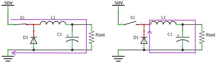
Buck regulator
A buck regulator is a switching power supply that makes convenient use of the
stored energy in the coil. To explain how the buck regulator works, let’s look at the above illustration. Here is how it works:
1. The switch is closed and the coil starts up. An increasing current flows through the load resistor. The bucket capacitor is filled; the diode is in reverse. The power supply delivers the load current and the charge current for the capacitor.
2. The switch is open, but the diode, in forward conduction now, allows the coil to release the stored energy to the load resistor.
A decreasing coil current flows through the load resistor, which is replenished as the bucket capacitor empties.
3. By properly choosing the switching times and capturing the voltage variations with a capacitor, we can determine the output voltage. The buck regulator is widely used to convert a high DC voltage into a stable lower supply voltage. It is reliable and has high efficiency.
Current, Voltage and conduction
Conductors
A conductor is a material through which electrons can move easily. This would usually be a metal such as gold, silver, or copper.
Voltage
Voltage is the electron pressure put on the conductor by a voltage source. The symbol is U and the unit is volts (V).
Voltage source
To make electrons flow, we need an electron pump, i.e., an electrical power source. Examples of this would be an alternator or a battery.
Such a battery or dynamo supplies a voltage with the symbol U, and the unit is in Volts.
A battery supplies direct voltage. An alternator usually supplies an alternating voltage.
Direct current
Current, represented by the symbol I and measured in Amperes (A), refers to the flow of electrons through a conductor. We measure this by quantifying the charge of the electrons flowing through. When the current consistently flows in one direction, it’s referred to as direct current and correspondingly, the voltage is termed direct current (DC) voltage. Though we typically assume current flows from positive to negative, this isn’t actually correct (see Historical error). Regardless, it doesn’t impact the calculations we do.
Circuit
Electrons require a circuit to flow. Current travels in a closed loop: it starts from a power source, passes through a load, returns to the power source, and then flows back to the load again. This continuous loop is referred to as a circuit.
Each circuit has resistance (except in super rare cases like superconductivity) represented by the symbol ‘R’ and measured in Ohms (Ω). Resistance is present in both the load and the power source. The power source’s resistance is known as the internal resistance, which should ideally be as low as possible.
Ohm’s law always applies to any resistance within a circuit: Voltage (U) equals Current (I) times Resistance (R), or U = I x R.
Lastly, remember that almost all electronics use direct voltage as their power source.
An example of a circuit: the battery pumps electrons around. The electrons flow through the battery via a conductor to the lamp, through the lamp and back to the battery. The energy used by the lamp is supplied by the battery until the chemicals that drive the pump are completely used up. Of course there is no combustion engine in the battery, but a chemical motor. The illustration is just to show the principle.
Digital.
Your telephone, the television, your computer (of course), and many other devices are equipped with processors. These often come in the form of microcontrollers (for more information, see the entry on microcontrollers). A processor can only process digital signals. That means most electronics operate digitally. Digital signals only have two values: on and off (or, to put it in computational terms, one and zero). So, analogue signals such as light intensity or volume must first be digitized before they can be processed or stored in your phone or sent by Wi-Fi.
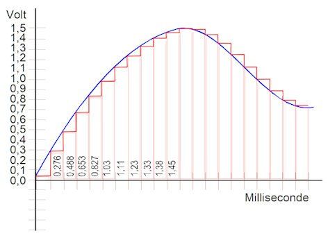
To digitize a rising and falling volume (as an example), we break time down into a set of chunks. At (for instance) each 1 microsecond step, the volume gets measured and saved as a digital number. That’s right; on your PC, the volume is like a chart with a unique number for every microsecond! This sequence of digital numbers can be stashed away in the memory.
The same can be done with colours, amount of light, you name it. By the way, there are several ways to translate analogue values into digital values. The end result is always a staircase trend (like in the graph we’ve just seen), so it will never be exactly the analogue value! The big advantage is that with digital signals you have almost no noise (see Noise.)
Digital number
What do digital numbers look like? Ever wondered how we humans learned to count? You won’t believe it - it’s all about our fingers! We have ten of them, so it makes sense that we can countup to ten (zero, of course, stands for no fingers raised). But what happens when we run out of fingers? Simple! We remember that we’ve counted one complete set of ten fingers and start counting from one again. This laid the foundation for our numerical system, which is based on tens. Here’s an example: Imagine you’re trying to secretly tell your buddy the answer to an exam question (not that we’re condoning cheating!). If the answer is 23, you’d raise your ten fingers twice (2 x 10), and then raise three fingers. So, 23 is essentially two tens (twenty) and a three. But when we reach ten tens (10x10), our fingers “run out” again, and we progress to using three digits instead, moving into the hundreds. In every group, we always count up to 10. Isn’t it cool? We call it the decimal system. Computers have an even trickier time than we do, but smart systems allow them to process numbers extremely well. Imagine a computer only has “one finger”, used to make a zero (no raised finger) or a one (finger raised). What about two? Here’s the thing. The first slot can only count up to one (remember, the computer can only use 1 finger). So for two, the computer needs to go to the next slot and then uses the same lone finger to make a two. Effectively this is saying “nothing in the one slot, and one thing in the two slot; so, our total is two.” With two recorded, it can start with one again, getting to three (using two plus one). Then the first two slots are used and for the number four the computer has to shift to the next slot. As a result, computers calculate in multiples of twos. Sounds strange? Well, that’s the binary or dual system for you! See table 1.
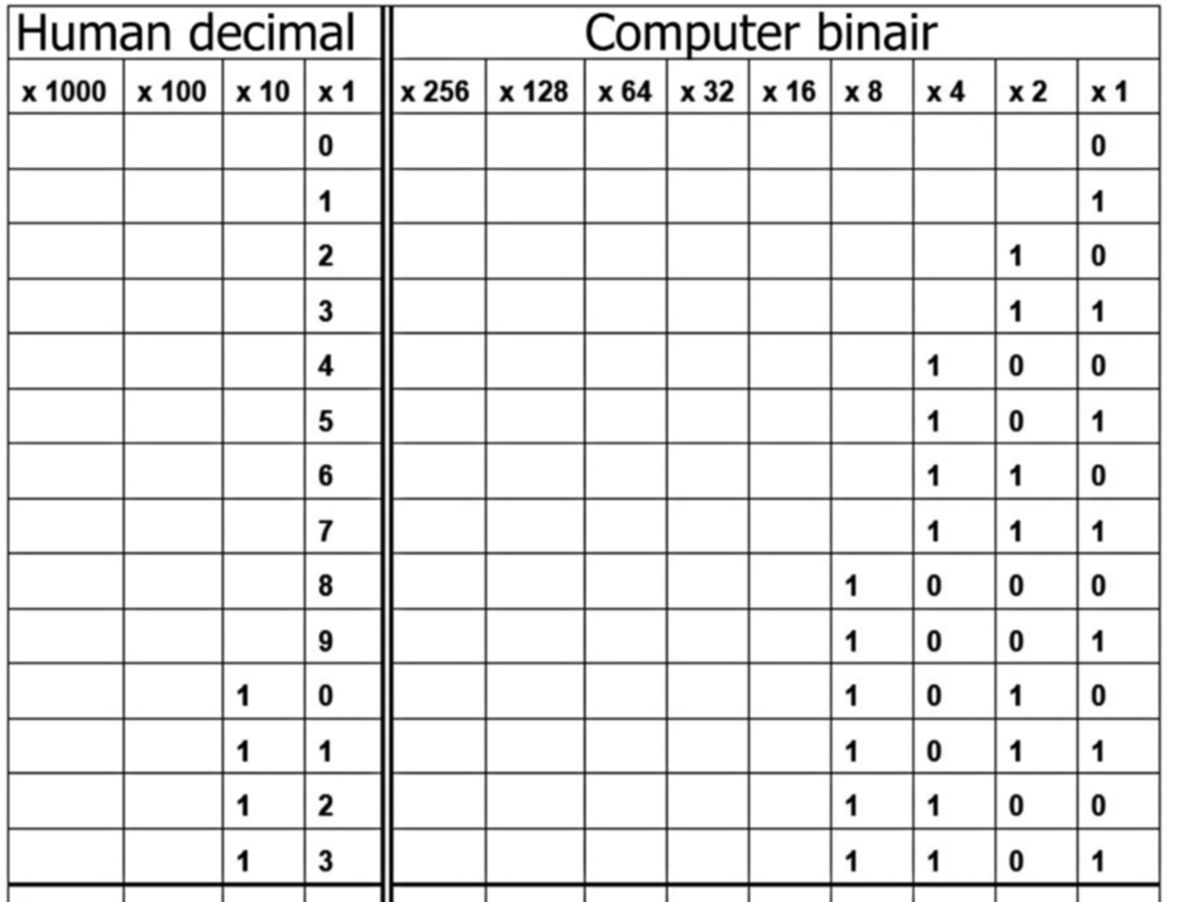
Table 1. Here’s how we humans count up to 13, shown alongside the way computers do the same.
Binary arithmetic is also quite a bit more cumbersome.
You should only go through the following parts if you like them, otherwise you rarely or never use them.
Binary addition:
Suppose we want to add the binary numbers 00001011 and 01101010.
This actually works just like decimal addition (the ten-digit system), but with memorization for each digit:
00001011 = 11decimal
01101010 = 106 decimal
We start on the right, just like ours. 0 1 is of course 1. At the second digit we find 1 1.
That would be two, but that doesn't fit in a digit, so we say: remember 0 and 1.
At the third digit we find two zeros, which is of course zero, but we still remembered 1, so that becomes 1. The fourth digit is again 1 1, which means 0 and 1 are remembered. The fifth digit is 0 0 = 0 plus 1 of the previous digit is 1.
Digits 6 and 7 are both 1 and digit 8 = 0
So the result is 01110101 = 117 decimal
If you want, you can add decimals again and you will immediately see the agreement.
We move on to the ten because we have ten spots, the computer goes directly to the 1 because it only has one spot (light on, light off).
Now another example of multiplication.
I first give the numbers that the digits stand for:
128- 64- 32- 16- 8- 4- 2- 1
Bit 0 represents 1, bit 1 represents 2, bit 3 represents 8, bit 4 represents 16, and so on.
If we now multiply 11 by 106, the following happens:
01101010
00001011
For convenience, I put 11 at the bottom and left out the multiplication by 0.
As with us, we multiply each digit of the bottom number by the top one
The result of bit 0 = 1x106 = 01101010
The result of bit 1 = 2x106 = 212 = 11010100
The result of bit 3 = 8x106 = 848 = 1101010000
If we add all those numbers together, we get 1166 or 11x106. = 10010001110
In any case, you now understand where all those strange numbers come from when we talk about computers; they are always powers of 2!
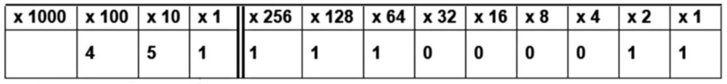
Table 2. 451 Broken down, left the human way in multiples of ten, right the “computer” way in multiples of two.
Pretty clear that computers need more “slots” to store decimal numbers in binary, right? For the number 451, which only takes up three places in our heads (a four, a five, and a one), a computer needs a whopping nine places! That’s why computers have to handle so much data when working with our kind of numbers or characters.
Diode
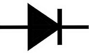
A diode is a component that passes current in only one direction. The symbol for a diode is – quite appropriately – an arrow. The arrow points from anode to cathode, and thus the current flows from anode to cathode. The symbol has quite a few variations, such as an open arrow or an arrow with a line through it, however they all stand for the same component.
Water model of a diode
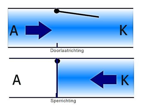
You can think of a diode in terms of the water model. It acts like a tube with a valve; the water can only flow in one direction. If the water flows one way, the valve opens and water can flow through. If the water flows the other way, the valve closes and no water can flow. You then say that the diode bars the way for the flow.
Before the valve opens, the water must already exert some degree of pressure in order to lift the valve. This is exactly how it is with the diode. If we connect the voltage in the forward direction, the diode always loses some voltage in order to keep the valve open. With a diode, this is called forward voltage (FV) or forward voltage loss. This voltage varies by type of diode, from 0.2 V to as much as 3 V.
You have to take into account that when the diode bars the flow of electrons, the valve can only handle a certain amount of pressure (voltage). Beyond that, it breaks down. This is why a diode always specifies the maximum reverse voltage. Another thing to keep in mind: The valve never closes a 100%, allowing a very small amount of current to flow in the reverse direction. This is called the leakage current.
Again, of course, there are many different diodes, with the reverse voltage, forward voltage loss, and maximum current being their most important characteristics.
Something that is easily forgotten is that a diode, when it passes current, also generates power in the form of heat through the forward loss voltage. As an example:
A current of 3 A flows through a diode with an FV of 1 V. The power generated is 1 x 3 = 3 Watts! (P=U*I). This is why we like to choose types with low FV for diodes when a lot of current has to flow, otherwise your circuit is going to get very hot and will require more cooling
Applications of the diode
The diode is used wherever you want to convert an alternating voltage into a direct voltage (see rectifiers). Diodes are also used to prevent voltage drop in a line.
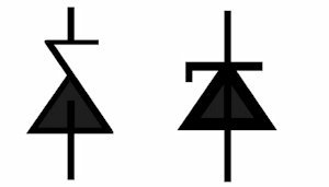
Zenerdiode
A zener diode has as the symbol of a diode with a broken reversal stripe.
And that’s a fair description of what it does. If you connect a standard diode in reverse, it breaks down when the voltage gets too high. A zener diode is a diode that trips at a certain voltage without breaking down.Of course, the current should not be too high and a good current limiter is essential. But the nice thing is that you can create a fixed voltage this way. Zener diodes are almost always used for that purpose. For zener diodes, the zener voltage is given, of course, but also the maximum power, the minimum zener current, and the possible voltage deviation
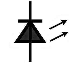
LED
LED stands for light-emitting diode. So a LED is a diode that emits light. This is reflected in the symbol. The nice thing about LEDs is that they lose much less energy as heat compared to typical light bulbs.
With an incandescent bulb, only 5 to 10 percent of the supplied energy is converted into light, the rest is burned up in heat; a pity if you don’t need that heat! With modern LEDs, at least 50 percent of the energy is converted into light. LEDs are available in many colours. One disadvantage is that LEDs
generally have a high forward voltage. And that means you cannot drive LEDs with a low voltage of, say, a 1.5V battery.
A LED is ideal for small appliances like remote controls, doorbells, etc. Unfortunately, you always need at least two space-consuming batteries in series to power these.
Dynamo
A dynamo, or alternator, is also (erroneously) called a generator. A dynamo is a device that allows you to convert mechanical energy into electrical energy.
However, a generator is the combination of an alternator and a drive using another energy source to let it turn; a diesel engine for example. There are multiple electronics symbols in use to represent alternators, since there are multiple types of alternators. In a circuit diagram (also called a schematic) you often will see an A (meaning alternator) or a G (meaning generator, which implies a motor is included) instead of a sine symbol.
First read everything about the coil, you'l need this knowledge to properly understand the alternator. We need to understand coils because a dynamo consists of a coil and a magnet. Either the coil or the magnet is moved such that the coil is in an alternating magnetic field. This causes the electrons in the coil to roll back and forth, creating an alternating voltage on the ends of the coil. The deeper the coil is in the magnetic field, the better the output of the dynamo. You can find a simple dynamo project in project 4 “The drain pipe dynamo”. As was mentioned, there are many types of alternators, but the basic principle is the same for all of them. The main difference between types is that, through many clever inventions, we now have very efficient alternators that can range from ones providing a very small output, to those that can provide huge outputs of up to 2 trillion watts
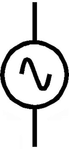
symbol for a dynamo
Driving the alternator.
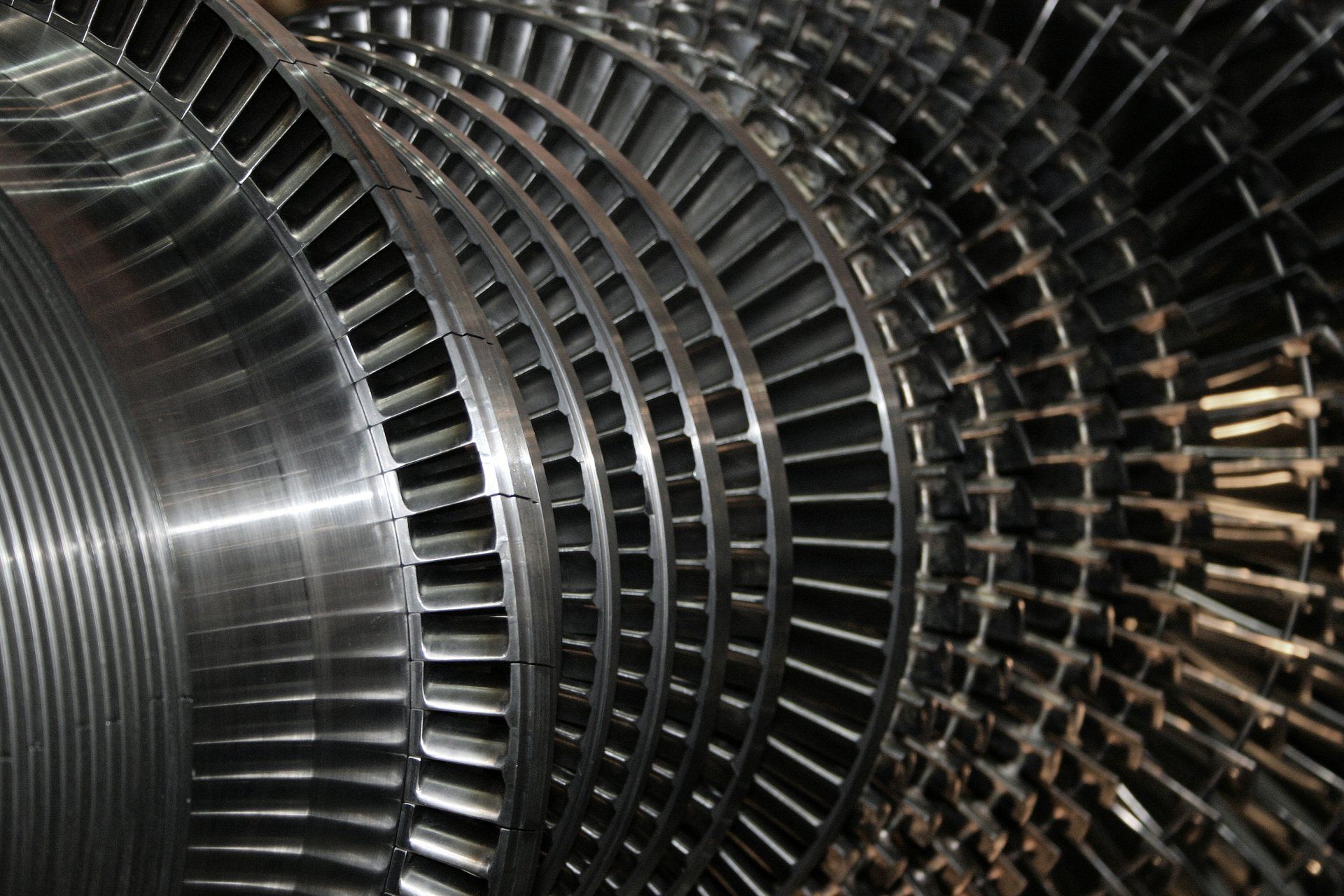
An alternator must be driven, that is, something must turn the magnet or coil. Remember, we said that you only have a generator once you have both alternator and a drive. Most smaller generators use a gasoline or diesel engine to do this. But there are also many generators that are powered by turbines.
A turbine
is similar to a water mill. Water or steam pressure causes the mill to turn. An example of a modern turbine is the paddle turbine found inside large dams that give us hydropower. The water in front of the dam is blocked so that it becomes very deep, meaning that the water level is far above whatever is on the other side of the dam. By letting the water flow down from a great height, it pushes down upon the turbine with great force, large enough to drive the huge dynamo inside the dam. Because no pollution is caused while generating energy using this process, we sometimes refer to hydropower as white coal. The ultimate source of this energy is the sun. Energy from the sun causes the ocean water to evaporate and be carried as clouds by the wind. The clouds rain down over the mountains, replenishing the water in the reservoir. Sounds like a perfect form of energy production, right? Unfortunately, the construction of a dam also often has far-reaching consequences for the surrounding area and the environment, so it’s not a perfect solution that we can just build everywhere.
And if there are no mountains or reservoirs available, energy has to be generated using a different approach. A good alternative energy source is wind, and we can build dynamos in windmills. But most of our electrical energy is made using steam turbines: Turbines driven by steam pressure. Steam is made by heating water. That heating is done in combustion chambers, which burn coal, natural gas and/or biomass, or by nuclear reactors.In a nuclear power plant, the steam pressure is created by nuclear fission. This does not release CO2 or particulate matter into the air. That is a very nice energy source! Unfortunately, up to 75% of the heat disappears in the air and in the cooling water . Other problems of a nuclear power plant are the radioactive waste, which continues to release deadly radiation (not electromagnetic radiation) for thousands of years, and the major risks in the event of accidents. The nuclear fission process can go uncontrolled in an accident, releasing enormous amounts of radioactive waste into the air or water. That is not imaginary, the disasters with the nuclear power stations in Chernobyl and Fukushima still have enormous consequences. What is less known is that more nuclear disasters have occurred, including:
Sellafield, Great Britain – 1957
Idaho Falls, Idaho, United States –1961
Jaslovské Bohunice, Czechoslovakia – 1977
Three Mile Island, United States – 1979
Ibaraki Prefecture, Japan – 1999
Nuclear energy does not cause air pollution, but there is still a lot of invention to be done before we can use nuclear energy safely.

Even lightning is easily absorbed by earth.
Earth/Ground
In electronics you often come across the words earth or Ground (GND).
You probably already know that this has little to do with garden soil or potting soil. What is meant by earth? Suppose you have a small steel ball. You stuff electrons into the sphere. What happens then? The electrons are distributed as evenly as possible over the sphere and the sphere acquires a negative charge. An electron is extremely small, so you cannot even measure the first few thousand electrons that you stuff into the sphere. The planet earth on which we live is also more or less a sphere. That sphere contains many substances such as water with salts dissolved in it, minerals including metals, and so on. Many materials that conduct reasonably well. The planet Earth is a huge sphere. If you pump a few billion electrons into it, the result is not even measurable. Sometimes you can see billions of electrons being pumped into the Earth when lightning strikes. Yet the earth receives next to nothing charge.
You can think of the earth as a huge vessel into which we can pour all the excess water, or, if we need it, take it out. In electronics we use the earth as a storage place for electrons. The earth as a huge capacitor. If we want to protect circuits or electrical equipment against voltage peaks, we ensure that those peaks can easily flow to earth. For example, the washing machine in your house is also grounded. If a wire breaks in the washing machine and 230 V appears on the outside, it flows immediately to earth so that the washing machine remains safe. How?
Yes, it really is true that we stick a well-conducting pin deep into the ground for this. Most houses have their own earth pin.
Electromagnetic waves
Electricity and magnetism are basically twins; where you find one, you’ll find the other. When you put an alternating voltage through a wire, electromagnetic waves are created. Those waves consist of a magnetic wave (red in the picture) and an electric wave (blue in the picture). They are connected and at right angles to each other. Those waves fly in all directions, and right through most things. If you make a bundle of those waves, with a parabolic mirror found in a flashlight, they mainly fly in one direction. The light we see also consists of electromagnetic waves, so, you can see those waves very easily with a flashlight: The beam of light from your flashlight is also a beam of electromagnetic waves. (Try it, preferably on a foggy evening, and you will see the whole beam). Electromagnetic waves, like other waves, have a wave height and a wavelength. The wave height indicates the strength of the wave, and is called the amplitude. The wavelength can vary from kilometres in size, to far smaller than a millimetre, depending on the wave. As humans, our sight is limited to a very small band of wavelengths between 300 and 700 nm, in which we perceive the three primary colours of blue, red, and green. Other colours that we can see are combinations of these. Most of the electromagnetic waves we cannot see. Electromagnetic waves are often called radio waves because they are used to transmit speech and music. Nowadays, radio waves are used for anything we want to send without a wired connection, such as Instagram and WhatsApp.
Electromagnetic spectrum
If we list all possible frequencies of electromagnetic radiation, neatly sorted from low to high along a line, we would call that a spectrum. Thus, the electromagnetic spectrum is the sorted collection of all possible frequencies for an electromagnetic wave. The electromagnetic spectrum is extremely large, the longest wavelength being about 100,000 km, while the shortest is about 1 trillionth of a meter. In electronics, there are only a few values from the spectrum that you will frequently encounter. It is good to know that there are more frequencies than just 2.4 GHz and 5 GHz, but you certainly don’t need to know the spectrum by heart. If you want to know exactly what the spectrum looks like and what its range is, you can find the whole spectrum here.
Https://en.wikipedia.org/ wiki/Electromagnetic_spectrum
A strange problem.
If you make a wave with a rope, for example by moving it up and down with your arm, the forward motion is easy to understand, because the upward motion of your hand pulls up the rope particles, which then pull the next rope particles along with them, and so on. But electromagnetic waves fly straight through empty space. And there are virtually no particles to pull on there at all! Therefore, sound cannot fly through space; in the vacuum of outer space you hear nothing! But the strange thingis that all electromagnetic radiation is able to simply fly through space. This is only possible if that radiation itself consists of a stream of particles. Those particles are called photons. In physics we sometimes use the wave property to describe electromagnetic radiation, and sometimes the particle property, whichever is convenient.So, what are photons? As you know from my previous letters, electrons move in shells around the nucleus of the atom. When an electron jumps to a lower energy shell of its atom, a very small amount of energy is released, and we call that a photon. Light flying through the vacuum is made up of those kinds of very small energy packets.
Seeing infrared:
We humans cannot see infrared, our eyes simply don’t have the right sensor cells for that. Infrared is in the part of the spectrum invisible to us. But there is a trick you can use to see infrared anyway. Use your cell phone’s camera to look at the TV remote control. Change channels.... Your cell phone’s camera picks up easily the infrared radiation and the display shows it as white light we can see. Thanks to your phone, you can still see infrared!
Energy and power
Energy is a very special thing. No one really knows what it is. If you have a lot of energy, you can do a lot of things. You need energy to move, to make heat, to make light and many other things. You could say that energy is the source of all physical work. But where does energy come from? Nobody knows the answer. At the moment we think that all the energy in the universe has always been there and will always be there. Energy comes in many different forms. But not all energy is attractive and/or useful to humans. Energy in the form of heat is our best friend, but in electronics it is almost always our worst enemy. Because everything in electronics is based on the movement of electrons, heat is generated everywhere. All components get hot. Not only is this a waste of precious energy, it also causes many problems. Devices and components must always be cooled to prevent them from getting too hot.
Energy in the form of electricity is very useful to us. All electronics use this energy. Unfortunately, apart from lightning, there is no natural source of electricity on Earth. This means that we have to make electricity from other sources, such as wind or solar energy. Coal, gas and oil are natural sources of energy. To make electricity from them, they are first converted into heat (by combustion) and then into pressure to drive turbines, which in turn drive dynamos. Hydrogen is not a natural energy source, but rather a form of storage. If you want to use hydrogen as a fuel, it must first be produced using electricity
Since the energy has to be generated in a power plant, it has to be paid for. It is therefore important to be able to measure and calculate the amount of energy. The consumption of energy is called power. The power of a DC voltage is calculated by multiplying the voltage by the current: P = U*I
For an alternating voltage the formula is P = Ueff*I
(see alternating current). The unit of power is watt.
To calculate the amount of energy used, we multiply the power by the time the power is used: E = P*t
The unit is watt-hour, mostly expressed in kilowatt-hour
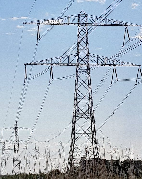
Transport of energy
Power has to be transported like any other good. The power plant makes electricity that is then sent to customers via high-voltage lines. The high voltage is then reduced to 230V AC and transported to homes and businesses. In your home, the power comes in at the meter box and then goes to the sockets. From there, the power is fed through a cable to electrical appliances. These devices adjust the voltage and send the power to the components. At the end of the process, the power is distributed to printed circuit boards via power supplies. All this transport causes some losses and disturbances, which we need to think about.
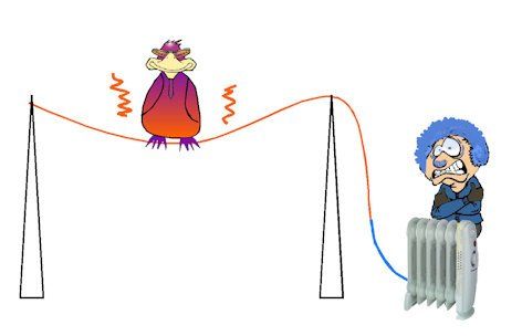
Cable losses in energy transport
All materials, including good conductors, resist electric current. Put simply, all conductors have some resistance. Now, imagine we roll out a kilometre of copper wire with a total resistance of 1 Ω. We use a 10V direct voltage. If we want to transport 100 watts of power over a kilometre of copper wire with a resistance of only 1 Ω, we need to deliver a current of 10 A. The law of Ohm tells us that the voltage drop across 1 Ω at 10 A is 10 V. This means that at the end of the cable, all the power is used up and nothing is left for the user!
Therefore, we do use high voltages to transport electric energy. Take a look at the following calculation: In stead of 10 Volt, we are using 1000 Volt. To deliver 100 Watts of power we now only need a current of 0.1 ampere! The cable loss therefore is decreased to 0.1 x 1 = 0.1 V. and 0.1 x 0 .1 = 0.001 Watts. Plenty of energy left for the customer!
Ferrite
Ferrite is a ceramic material in which metals are mixed. Ceramic means a material that, like porcelain, can be fired in an oven so that it becomes very hard. Teacups are made of fired clay or porcelain. Those are ceramic materials.
These, of course, do not conduct. Thanks to the mixed-in metals, ferrite can conduct magnetic fields very well. Because it is ceramic, it can be made into any shape before being baked in an oven. After that, ferrite is enormously hard and strong. Ferrite is made specifically for its magnetically conductive properties. Ferrite is used in coils to strengthen the magnetic field. With ferrite, you can adjust the value of a coil by putting in more or less ferrite. Because ferrite conducts magnetically very well, it is also used as a choke coil. High frequency signals are short-circuited in the ferrite and thus choked or attenuated. DC or low frequency AC signals will pass easily. You can find this application as ferrite cores around power cords for appliances but also as ferrite beads on circuit boards

Filters
Filters are used to block out junk, so that you are left with a pure substance. Dust filters, for example, remove dust from the air, so that you can breathe clean air. In electronics, filters actually do no different. Electronic filters remove clutter from your signals. A common type of clutter, for example, is noise. You can use noise filters to deal with that. If you have too much treble in your headphones, you can filter it out. With coils, resistors and capacitors you can build many different filters . Filtering is an extensive part of electronics. Following are some simple examples.
RC-filters
RC filters are made using a mix of resistors and capacitors. Resistor values stay the same, regardless of the frequency,
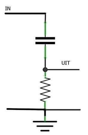
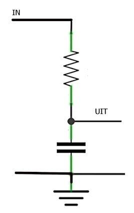
while the AC resistance (impedance) of capacitors change based on the frequency. The higher the frequency, the lower the impedance of a capacitor. For the full scoop on capacitors, check out our entry on them. We can use a capacitor and resistor together as a voltage divider to create basic filters. Try to imagine a voltage divider (See voltage divider) with a capacitor in place of the “top” resistor. For the high frequencies, the capacitor has a very low resistance; they zip right through. Instead, for low frequencies, the capacitor is a high resistor so there is not much voltage left after the voltage divider. Congrats! You’ve just built a highpass filter. Change things up
a bit and let the resistor and capacitor swap places. Now it’s an entirely different story. All the high frequencies trickle down to zero, and it’s the low frequencies that pass with ease. Well done — you have crafted a low-pass filter.
LC-filters
Coils are great at resisting alternating current. The higher the frequency, the better they block this type of current. That’s why coils often come in handy when we want to stop alternating currents, like interfering signals. A coil used this way is known as a ‘choke coil’ because it stifles the interfering signals. In the day-to-day practice of electronics, this coil often shows up as a ferrite bead, usually employed to suppress interference pulses. These days, ferrite beads come in SMC form. To know more, you can take a look at our entry on Ferrite.
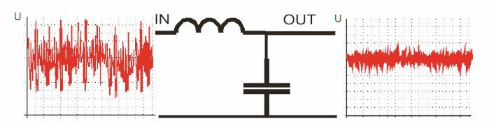
Picture combining a coil (L) and a capacitor (C) into a voltage divider. What you’ve just cooked up is a combo that not only stifles interfering signalsBefore (on the left) and after the LC filter.but can also short circuit them to the ground, thanks to the capacitor. This setup creates a powerful filter, though it’s a bit more complex when it comes to calculations and adjustments.
Force
If we look closely around us, we can see forces at work everywhere. Anything we throw into the air will fall back to earth. The earth attracts (or pulls on) all objects upon and aroud it. We call that gravity. If we hold two magnets together, they will push each other away or attract each other. We call that the magnetic force.
Something that pushes or pulls on an object is called a force.
Four basic forces have been found (so far):
The weak nuclear force ensures the energy exchange within the atomic nucleus.
The strong nuclear force ensures that the atomic nuclei stay together.
Gravity ensures that everything remains on the Earth and that the planets remain in their orbits.
The electromagnetic force ensures that the electrons remain around the nucleus of the atom. This power makes our electronics possible.
Forces are very mysterious, they are invisible and no one knows exactly why they exist.
fighting gravity
Fuse
A fuse is a handy device used to keep a circuit from experiencing too much current. Picture an old-school fuse that you might uncover if you were living in a house that was built during your grandma’s era. It’s pretty simple—just a glass tube with a super thin silver wire inside. If the current gets too high (above a certain limit), that little wire goes “poof” (literally burns out), stopping the current flow and keeping the circuit safe and sound.
When you’re looking at diagrams, a fuse is shown as a rectangle with a melting wire inside. Beside it, you’ll see the current limit—the number that tells you when the fuse will burn out. There’re a couple of types of fuses to know about. The slow fuse (S) does what the name implies—it holds out for a bit before burning up. Then there’s the fast fuse (F)—it’s quick to burn out, doing so instantly once pushed over its limit. But it’s not all vintage tech. These days, we’re working with fresh materials to build tiny fuses, which can be soldered directly onto a printed circuit board (check out the entries on PCBs and surface mount components). One major upgrade is the self-healing fuse. When the current gets too high, instead of blowing up, these fuses increase their resistance, essentially putting the brakes on the current. And if the current dips back down, the resistance lessens. Way better than traditional fuses that need changing every time the current spikes!
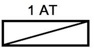
Fuse symbol
Heatsink
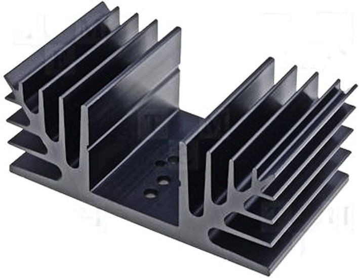
In electronics, heat is almost always a problem rather than a benefit. As electrons run through the components the components get hotter and hotter, and eventually break down from overheating. This is why most components always have a maximum power rating listed. The parts lose their heat to the air over time; this is why machines like computers have fans to blow away hot air and bring in cooler air, which will take away the heat more efficiently. In special cases, water cooling is also used, since (cold) water is great at sucking up heat. Unfortunately, most components are in a plastic housing, which makes them harder to cool. This is understandable, because you don’t want the part to accidentally make contact anywhere. You also want to protect the important metal materials in your machine from oxidation (i.e. getting rusty). Plastic is not a good conductor of heat, meaning it won’t take away the heat from the metal component at any decent rate. That’s why parts that need to handle high levels of power often have metal plates in the plastic. Those plates conduct heat and are exposed to the outside air, allowing the part to cool much more quickly. The greater the surface area over which air can flow, the better the part can dissipate its heat. Therefore, you can help the part cool faster by making the cooling surface larger. Then, of course, you have to use a material that conducts heat well, such as copper or aluminium. Aluminium is cheaper and lighter than copper, which is why that material is most commonly used to make the cooling surface larger. There are many cleverly devised shapes of aluminium that you can attach to your part or vice versa to enlarge the cooling area. Those shapes are quite appropriately called heatsinks. The specifications of a heatsink state how much the temperature of the heatsink rises per added power in watts. In Europe, we use °C/W. The lower this value, the less the temperature rises, the better the cooling capacity!Most components come with documentation telling you the maximum temperature at which they still work well. You can, of course, calculate the power from the circuit, and in turn, you can calculate how big the heatsink should be. To do this, you divide the allowable temperature rise by the power.
Here is an example:
A transistor KD880 has a collector voltage of 12 V. The emitter voltage is 4 V. The current is 2 A. The maximum safe operating temperature is 60 °C.
The ambient temperature is 20°C. Across the transistor falls 12 - 4 = 8 V. The power the transistor must convert to heat is 8 V x 2 A = 16 W. The transistor is allowed to heat up a maximum of 60-20 =40 °C. So, you need to mount a heatsink of 40/16 °C/W = 2.5 °C/W.
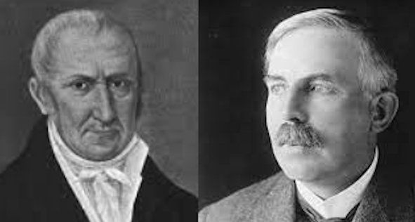
Historical error
Alexander Volta invented the first zinc-copper battery in about 1800. The scientists at the time thought that the current flowed from plus to minus and therefore always opted for that. Only much later (about 1860) did a Mr. Rutherford discover that electrons have a negative charge. And... it is the electrons that can move through a conductor. The electron flow therefore runs from minus to plus! This makes no difference at all for all our calculations and we therefore continue to use the conventional current from plus to minus.
An integrated circuit, in this case a microcontroller.
Integrated circuits
Thanks to the very large, important Dutch manufacturer ASML, parts can be made increasingly smaller due to advances in technology. Manufacturers can therefore stick many thousands of parts together on a very small surface. We call these integrated circuits or ICs. Very large integrated circuits will of course become hot, so significant cooling is required. By continually lowering the operating voltage (again through advances in technology), manufacturers try to limit the power (P =U*I). Large processors, such as the I7 from Intel, have approximately 2 trillion MOSFET’s on board of one integrated circuit!!!
(For further details, read the entry about transistors and mosfets). Only one simple IC is used in the example circuits of the book. There are thousands more to discover!
Logic circuits
The word logical is used for a lot of things, but in electronics it has a very clear meaning. A logical circuit is a circuit where you can put zeros and ones into and where zeros and ones come out. A logic circuit always reacts the same to the zeros and ones you put in it. A zero and a one are always a fixed voltage. In 5 V logic, for example, this is
0 V and 5 V. Logic circuits therefore work in binary mode. There are just a few basic circuits and they are very easy to understand and apply. You can come up with a lot of fun circuits with logic circuits.
Logic gates
A gate is an arch that you can walk under, sometimes with a door in it. You enter a gate and you come out the other side. And that's exactly how it is with logic gates. There are three basic gates, with which you can make many combinations.
The OR gate, the AND gate and the NOT gate. The Not gate has 1 entrance and 1 exit. The exit is always opposite to the entrance. That is why the NOT gate is also called an inverter. The common emitter circuit with the NPN transistor is in fact also a NOT gate. The OR gate has two (or more) inputs. The output becomes 1 when one of the two inputs becomes 1. An OR gate is very easy to make with diodes
The AND gate also has two (or more) inputs. The output becomes 1 when both inputs become 1. The AND gate is also easy to make with diodes.
Leaving aside all electronic limitations, you can (logically speaking) expand the inputs of the AND gate and the OR gate indefinitely.
So you can trigger an alarm if a 1 arrives at one of the many inputs of the OR gate, for example from a glass break sensor.
Or you can ensure that you can only make a decision together. If a 1 is missing somewhere on one of the inputs of the AND gate, there will be no 1 on the output.
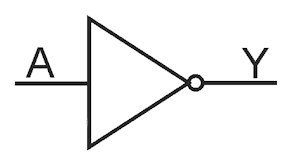
The NOT gate or inverter
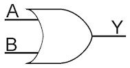
The OR gate
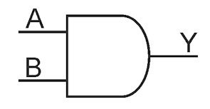
The AND gate
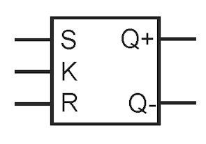
The flip-flop
In circuit 9 you will find a switch that switches every time you press a button. That's exactly what a flip flop does. A flip-flop is a logic circuit that switches the two outputs every time you operate it. Many variations of the flip-flop have been invented, but they all do the switching. Because a flip-flop has a logical hold switch, you can use it as a binary memory. Each flip-flop can remember exactly 1 bit.
There are many logic circuits for sale as integrated circuits. There are even integrated circuits (IC) whose logic functions can be selected by programming them.
Loudspeaker
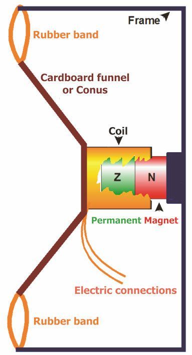
One of the most fun inventions made possible with a coil is the loudspeaker. It works as follows. If you send an alternating current through a coil, it becomes a magnet whose north and south poles constantly alternate. If you suspend this coil in the field of a permanent magnet, it is alternately attracted or repelled by the permanent magnet. The coil moves with the frequency of the current we send through it. Attached to the coil is a funnel made of light cardboard; the cone, which then with the coil will also move back and forth.The cone vibrates, which in turn makes the air vibrate. Vibrating air is what our ears pick up as sound. If the frequency is in the range audible to us, we “hear” the electrical signal that was sent into the coil, since it comes out as sound!
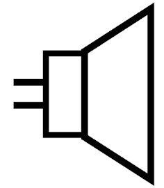
The principle of the modern coil speaker remains the same, simply lot of additional components that have been invented over time to ensure that the sound it produces sounds as natural as possible. The loudspeaker symbol is a simple representation of a loudspeaker. It states the resistance of the coil and the maximum power of the speaker. Data sheets often include a graph showing which tones are best reproduced.
The nice thing about loudspeakers is that the principle also works in reverse. If you vibrate the cone by sending sound to it, e.g. by speaking to it, the coil vibrates with it. The coil then moves back and forth in the magnetic field of the permanent magnet. As a result, the coil “sees” a changing magnetic field, and the electrons in the coil start rolling back and forth in tune with the vibration. The signal from the coil is the electrical version of the sound that caused it to vibrate! Such a sound sensor is called a microphone. To record sound as faithfully as possible, a microphone is built very differently compared to a loudspeaker, but the principle is completely the same. So, you can also use a loudspeaker as a microphone, but without all of the adaption made for a microphone the sound quality will be rather poor. Materials have now been invented that themselves shrink and expand instantly when you offer a negative or positive voltage to them. Piezo crystals, for instance. With these, you can make very small speakers and also tiny microphones. The ones that are used in mobile phones for instance.
Loudspeaker principle

Loudspeaker symbol microphone symbol
Magnetism
Magnetism is a force, although we have no idea why it exists or what causes it. What we do know is that magnetism has something to do with electrical power. A magnet always consists of a north pole and a south pole. Equal poles repel each other, while opposite poles attract each other. A magnetically sensitive material, such as iron, nickel, or cobalt, itself becomes magnetic when it enters a magnetic field.
The magnetic force is transmitted by magnetically sensitive materials. The object becomes a north pole magnet where it is touched with a south pole and vice versa. Once the magnetic force is removed, the object loses its magnetism again.However, if a magnetically sensitive object stays in a strong magnetic field for a long time, it itself becomes a magnet, meaning that if the object is then removed from the magnetic field, it remains magnetic. This is called remanent magnetism. Usually, the object loses this remanent magnetism again after a period of time.Objects that are forever magnetic are called permanent magnets.A wire, or better, a coil, through which current flows, also becomes magnetic. This is called electromagnetism. Electromagnetism and magnetism play a major role in our lives. Wherever electrical energy is converted into mechanical energy (e.g. electric motor) and wherever mechanical energy is converted into electrical energy (e.g. dynamo), these two forms of electromagnetism are used. See the drain pipe dynamo and mono-polar motor projects for simple examples.
Check out this cool trick:
Believe it or not, everything around us is within the scope of Earth’s magnetic field. Even though it’s pretty weak, it still has enough strength to mess with objects that respond to magnets. Start by grabbing a long, iron object - an old screwdriver maybe? Align it parallel to a compass needle. Here comes the fun part: give the iron a good whack with a hammer to pump in some energy. Be sure to distribute your hits evenly across the iron. You’ll start to notice that the iron gradually turns into a (sort of weak) magnet. Just remember, this trick only works with iron - don’t try it with copper, stainless steel, or anything else. And a word of advice: test if the piece of iron is attracted to a magnet before you start hammering at it - you don’t want to spend days hammering for nothing.
Measuring
Taking measurements may seem like a mundane activity, but if you stop to think about it, it is something very intriguing indeed. Measurements make invisible things visible to us, usually in the form of numbers and letters. In electronics, of course, we mainly measure current, voltage, resistance, and frequency. To do that, we need a sensor and a meter. A sensor is a component that converts a signal into a measurable signal. The simplest sensor is a resistor. When we send a current through a resistor, a voltage is applied across the resistor. The greater the current, the greater the voltage. Now our meter comes into play; with a voltmeter, we can then measure that voltage and always calculate the corresponding current. Annoyingly, the measuring resistor itself also obstructs the current, thus causing the measurement to not quite be correct..
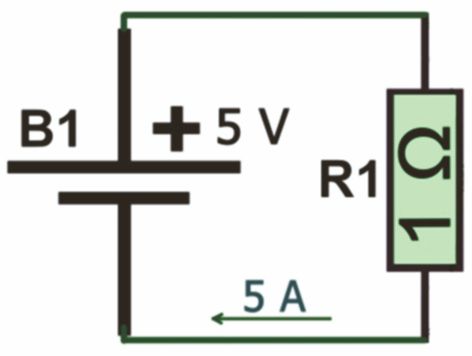
For example, we are going to measure the current through the circuit consisting of battery B1 and resistor R1. The voltage supplied by B1 is 5 V. R1 is 1 Ω. We know without measuring, thanks to Ohm’s law (U = I x R), that the current through R1 is 5 A. Now, we stick our 1 Ω sensor in the circuit. The meter only indicates 2.5 A! How can that be? Is the meter broken? No, the meter is working perfectly well. Thanks to our measuring resistor, the total resistance in the circuit has now become 2 Ω. And 5 V divided by 2 Ω is 2.5 A. Without the measuring resistor, the current is 5 A; with the measuring resistor, the current is 2.5 A. We have a measurement error as high as 50%! We therefore need to ensure that our measurement resistance is as small as possible when measuring current.
the real current
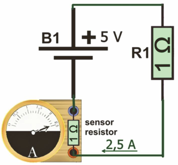
False current measurement
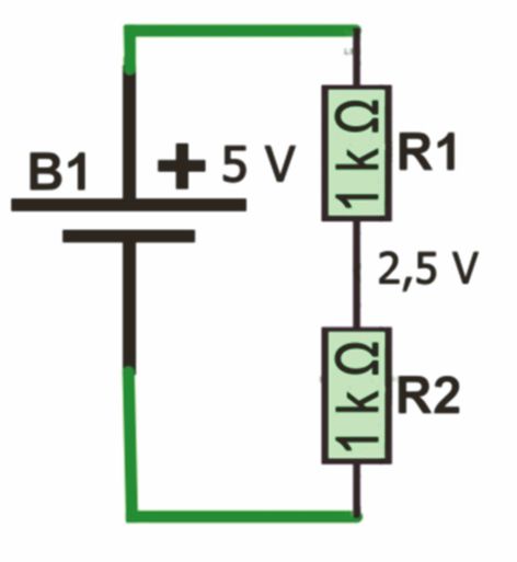
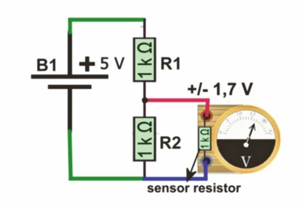
When measuring voltage we have a similar problem. The meter also uses a resistor as a sensor. That resistor will be parallel to the resistor over which we want to measure the voltage. The total resistance therefore becomes smaller. For example, you want to measure the output voltage of a voltage divider. The voltage divider consists of R1 and R2, both 1 kΩ. The battery supplies 5V. Thanks to Ohm’s law we know that the voltage across resistor R2 must be exactly 2.5 V. You connect the meter and it shows slightly less than 1.7 V! Is the meter broken? No, due to the internal resistance (sensor) of the voltmeter, there is now a resistance in parallel with R2. The total resistance there now becomes 500 Ω! The voltage is therefore only 1/3 of 5 V, which is approximately 1.7 V. Another significant measurement error thanks to the measuring resistor. That is why we use the highest possible measuring resistance when measuring voltage.
Measuring resistors also have a tolerance of their own, so they are not exact the value indicated, but slightly less or more. That “slightly” is defined by a percentage indicated on the resistor as well. (See Resistor). So, your resistor’s tolerance affects your measurement as well. The accuracy of your measurement therefore depends not only on your sensor, but also on your actual meter.
The real Voltage
False Voltage measurement
Nowadays we measure almost everything digitally. This means that we divide the time into very small steps of, for example, a millisecond and take a measurement every time a step has passed. We also call this 'taking a sample'. Each sample is represented by a number. We do this using an analogue to digital converter. By doing smart calculations (for example always taking the average of the last 10 samples) we get a value that we can display on a screen. If your meter can convert few samples per second, you will not see short voltage peaks. So you have to know exactly what the properties of your meter are to know whether the measured value corresponds somewhat to reality.
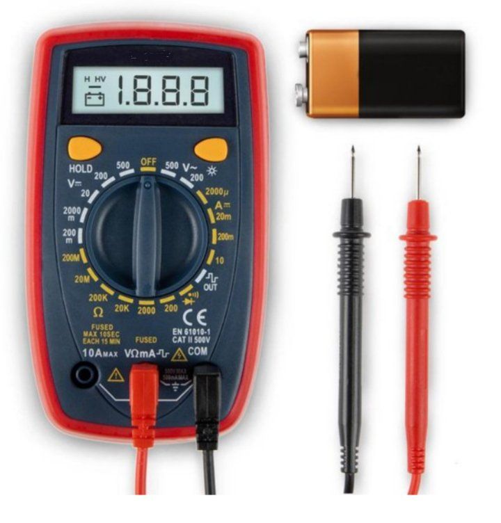
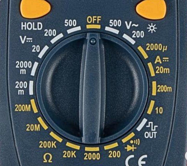
The universal meter
And now the most commonly used meter at the moment, the universal meter, also called a multimeter. Universal because it can measure many different things and often has a number of useful tricks up its sleeve. They come in all shapes and sizes and from very cheap to very expensive. If we take into account an accuracy that we can use for our purpose, you can have an excellent universal meter for a few tens of euros.
Let's take a look at such a meter. Again, there are many types and sizes, so each meter can look different. Above you will see a screen on which the selected function and the measurement result are visible. This often includes one or more keys to select additional functions. In the middle there is a rotary switch with which you choose a measuring range or function. Finally, at the bottom are the connection points for the measuring leads. What can such a meter do? We can see this conveniently from the switch with which you choose the functions. The button is now OFF, and you have to set it there every time you do not have to measure. The meter runs on a battery and if you leave it on the battery will run out! One step to the right the meter will measure alternating voltage with 500 V as a maximum. Another step to the right, the sensitivity is slightly greater and you can measure alternating voltages up to 200 V. You can then measure direct current from very accurately (2 mA full scale) up to 10 A. Please note, to measure 10 A current, the black measuring lead must be disconnected. connected to the current measuring input. This is the case with almost all multimeters. In the next step, the meter itself supplies a square wave voltage that you can use as a test signal. The next step is a whistle-through and diode test. The whistling causes the meter to beep when there is very low resistance between the measuring pins. For example, you can test cables. One pin on each side, if the meter does not whistle then there is an interruption somewhere. The diode measurement makes good use of the forward loss voltage of a diode. A good diode shows a voltage drop of between 0.3 and 1.2 V in the conducted direction and in the reverse direction the voltage is equal to the supply voltage, so much higher. The following steps let you measure a resistor in increasingly larger increments from 200 Q full scale to 200 MQ full scale. And finally, you can measure DC voltage with decreasing accuracy from 200 mV to 500 V full scale. That is already an incredible amount, for a meter that costs less than 20 euros. Let's look at the specifications, or how accurately does the meter measure? According to the specification, this meter measures DC voltage with an accuracy of ± 0.8%. Alternating voltage with an accuracy of ± 2%. Direct current with an accuracy of ± 2% and resistances with an accuracy of ± 1 to 1.5%. Measures 10 V. DC voltage, the actual voltage is somewhere between 9.84 V and 10.16 V. If you measure a DC current of 100 mA, the actual current is somewhere between 96 mA and 104 mA. It is therefore important that you know in advance how accurately you want to measure and how accurately you can measure. Bear in mind that with large values it is not useful to measure very precisely. If you want to measure the distance between Paris and Utrecht, you obviously do so in kilometers, not in millimeters. The thickness of a hair is measured in micrometers and not in kilometers. With the multimeter, the accuracy is given for the full scale reading per measuring range. In the 200 mA range the accuracy is ± 0.2% of 200mA, so ± 0.4 mA.
Microcontroller
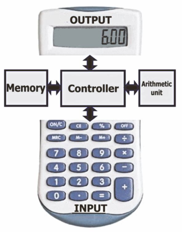
Think of a microcontroller as a calculator. The controller, the calculator’s heart, manages all operations. When you punch in numbers or commands on your keyboard, a translation occurs: these inputs are turned into binary language, the only language the controller recognizes. From this binary form, the controller can tell whether it’s dealing with an actual number or an instruction. Then, it figures out where to send this binary input. Options abound: it can safely tuck the number into its memory, or whizz it off to the arithmetic unit for calculation. If it needs to convey the number back to you, it sends it to the display unit, which acts like a translator. Here, the binary code is seamlessly converted back into a readable number. Who knew calculators could be so intriguing?
For instance, let’s say we’re calculating 2+3=6.
First things first, all inputs get translated into binary numbers, and outputs are always converted back into numbers that we can easily read.
So, let’s get started: you punch in the number “2” on your keypad. That sends the number in binary form (0010) hurtling towards the controller. The controller then tucks this number safely into memory while also flipping it over to the screen. And, voila! You see the number “2” on your calculator’s display.
Next, you hit the “plus” sign. This also becomes a binary number that the controller receives, recognizes as command, stows away in memory, and mirrors on the screen. Then, you punch in the number “3”. This similarly arrives at the controller, gets stored, and appears on your screen.
Finally, you hit the “equals” sign. The controller gets the message, recognizes
it as command, bundles up the 2, the 3, and the plus sign, and dispatches them to the arithmetic unit. Here, the addition operation happens, producing “6”. This result zooms back to the controller, which then serves it up to both memory and your eager eyes on the screen. And just like that, you’ve done a calculation in the secret language of your calculator!
So, these are the components of a calculator:
• The memory
• An arithmetic unit
• A traffic controller or controller
• Input device (keyboard)
• Output device (display)
The memory, arithmetic unit, and controller all bundled together in a housing (integrated, i.e. without keyboard and display) is called a microcontroller.
Moreover, a microcontroller has a program memory. Here, you can store a series of commands (binary, naturally) that the microcontroller executes. When the sequence ends, it loops back. This series of commands is known as a program, and crafting one is called programming.
In addition, a number of ports (interfaces) to the outside world are often included. The most well-known are the display interface (where the outside world can look at what the device is doing) and the keyboard interface (where you can tell the device what to do).
Modern microcontrollers are also packed with cleverly designed solutions, mostly to make them faster, more efficient and more reliable. There are many types of microcontrollers, all with their own special features and often their own language. You can create an endless number of applications with a microcontroller. It is indispensable for an inventor. For beginners, Arduino is a very nice device to start out with. Its language is easy to learn, and you can soon make really cool things with it. (See the fantastic website www.codingideaswithkids.com)
Modulating and demodulating
Electromagnetic waves (radio waves) travel at the speed of light. Therefore, if we can somehow pack messages into radio waves, we can send those messages at the speed of light, too. Packing a message into a light or radio wave is what we call modulation. The simplest kind of modulation is ‘on and off’. With a torch, you can transmit morse characters or ASCII codes (just like I did with Fred in my letter, “Bang chuka chuk!” page 70).
Even typically analogue things like music or images, as long as they are represented as electrical signals, can be packed in radio waves.
Packing messages in a radio wave might seem tricky, but it involves just two basic ways: amplitude modulation (AM) and frequency modulation (FM). Actually, it’s way simpler than it sounds!
A radio wave, which is an electromagnetic wave, has only two features: how long a full wave is and how tall. The wave’s height is called its amplitude. So with amplitude modulation, we’re basically changing the wave’s height.
As you may know, the human ear can hear frequencies from about 30 Hz to 20 kHz. A radio wave, by comparison, has very high frequencies, such as
2.4 gHz for Wi-Fi. That’s 2.4 billion Hz! Sound itself travels slowly (relative to light) and dies out quickly, but a radio wave travels at the speed of light and carries over huge distances. By fiddling with the amplitude of the radio wave to match a sound wave, the sound wave can hitch a ride along with the radio wave. This shows how adjusting the radio wave’s amplitude lets us send along a lower frequency. This radio wave, aptly named a carrier wave, trucks the lower frequency along with it. And because its amplitude changes around, this tweaking style is known as amplitude modulation, or AM for short.
Of course, you can also change the length of an entire wave section. By doing so, you change the frequency of the carrier wave. Again, the low frequency is hidden in the high. We call it frequency modulation, or FM for short. The picture is very exaggerated, usually the variation is very small compared to the carrier wave.So the trick of hiding the low frequency wave within a high frequency wave is called modulating. If you want to get the low frequency wave out again, you have to demodulate.
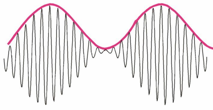
Amplitude modulation
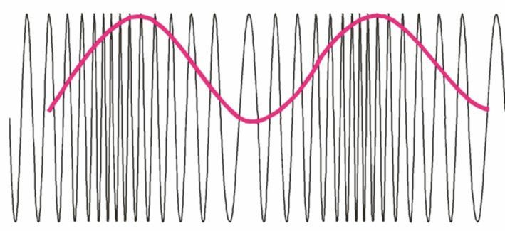
Frequency modulation
Morse code and ASCII code
Why ASCII code was introduced
Morse code is made up of short and long signals. These signals can be communicated in the form of light (for example from a torch) or as sound, in the form of beeps. So, how do we tell a short beep from a long beep? Simple - the long beep is at least three times longer than a short one! Additionally, there’s got to be a pause the length of one long beep between each signal. Quite tricky, don’t you think? Especially considering some folks can signal faster than others! Another thing with Morse code is the character limit. There aren’t as many as you’d find on a computer keyboard, for instance.The Morse code alphabet and the numbers 0 to 9. Morse code can be tricky and sometimes slow to work with. Why? Because there’s no fixed time to differentiate between the ‘zero’ (a short signal) and ‘one’ (a long signal). If you lose track, it gets confusing to figure out where one character ends and another one starts. Morse code isn’t exactly speedy, either. Every character needs a series of long and short signals. For example, digit ‘0’ requires five long signals! The more characters you want, the lengthier your Morse code signal gets.
ASCII code is a digital code meant for machines. ASCII code is a much better alternative if you have the equipment for it. Instead of a tone or light flash, we now send and zero or a one.
For the ones we make the line plus, for the zeros we make the line zero. The zero is 0 V and the 1 is a fixed voltage, e.g. 5 V.
An individual character consists of 8 digits, for example the character k is represented by the digital sequence:11001011 Using this method, you can create up to 255 characters, all of precisely the same length. Let’s compare this with Morse code: the Morse character for zero is made of five long signals that come with four short pauses. Combined, that equals the length of 19 short signals. On the other hand, each character in ASCII code is made up of just 8 short signals. When you’re communicating in ASCII code, every character starts with a pause of a specific duration known as the ‘start-bit.’ The character that comes up next is a mix of 8 bits (ones or zeros), all of the same duration—that duration is something both communicators need to agree on. After that, there’s a ‘stop-bit,’ marking the end of a character for a predetermined duration. Every message character follows this pattern: a start-bit, then eight character bits, ending with a stop-bit.
The start-bit is important for synchronisation:
Even machines with very accurate clocks never run exactly in sync. If you keep sending characters, the machines will eventually get out of sync and end up not understanding each other’s messages. Therefore, communicating machines start clocking each start-bit. The duration of the following character is so short that a small deviation between clocks makes no practical difference.The ASCII code has been greatly expanded to accommodate all the special characters, various languages and their unique characters, and the distinctive characters in mathematics and physics. As a result, the code was extended to 16 bits, allowing for the creation of up to 65,535 characters.
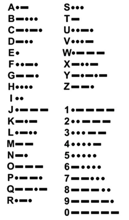
The Morse code alphabet and the numbers 0 to 9.
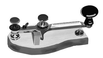
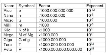
Multiplication factor
Electronics often involves working with very large and very small numbers. That is why multiplication factors are used. You have known some of them for a long time, such as kilo for 1000 times. A kilogram is 1000 grams, a kilometer is 1000 meters and a kilo-Ω (kΩ) is 1000 Ω.
Here you will find a handy overview of all factors used in electronics. The custom is to paste the symbol directly in front of the unit name.
1 µH = 10-6 Henry,
1 MgΩ = 106 Ω,
and so on.
Noise
If you close your eyes and listen carefully, you’ll find that the world is full of noise. You hear sounds from different sources: car traffic on the motorway some way off, an aeroplane passing high above you, birds whistling in the trees, the wind rustling through the trees, and so on. Background noise is what we call it. Your brain is perfectly capable of ignoring those sounds (unless you actually stop to listen to them) so that you can easily hear new or important sounds such as your friend’s voice.
Electrical signals also have noise.
That noise, like the background noise, comes from different sources. The heat movement of atoms causes resistors, transistors and amplifiers to produce noise. Switching power supplies creates lots of switching spikes on the power supply. Electromagnetic radiation is picked up by wires and/or PCB traces. All that noise is amplified along with the actual signal.
Sometimes the noise is so strong that the signal ‘drowns’ in it.

Digital technology offers a strong defence against noise. The reason? The signal can only be zero or one. This means the little noise signals are automatically left out. However, even digital technology isn’t foolproof. In the signal chain, zero isn’t exactly zero and one isn’t exactly one.
Therefore, limits are specified:
In 5 V logic, for example, ‘less than 0.9 V’ is considered zero and greater than 3.7 V is considered one. If a signal is 1, it only switches to zero if the voltage briefly dips below 0.9 V. On the other hand, if the signal is zero, it only turns to one if the voltage briefly goes above 3.7 V. The space between these two levels is known as hysteresis. All signals that fall within this gap are simply ignored. So, if your signal is 4 V, in this scenario, it counts as 1. It would only switch to 0 if a (noise) signal exceeding -3.099 V comes along! But really, 3V is a pretty solid voltage, so you won’t often see 3V noise.You may remember that
P = I x U, meaning that high voltages result in high power, which causes a lot of heat. Therefore, we aim to reduce the supply voltage, particularly in microcontrollers that use a lot of power and work digitally, to minimize power usage! However, there’s a snag. The lower the logic voltage levels, the smaller the hysteresis, making digital signals more prone to noise. Don’t worry, though. Clever inventors have been tackling this issue for a long time, so we can keep using lower and lower supply voltages.
Oscillation
You’ve likely experienced a microphone “whistle”—a piercing sound that drowns out every other noise. So, what causes this? It happens when the sound from the speakers feeds back into the microphone. For specific tones, the system amplifies the sound once, twice, or even more times. These tones go in a continuous loop, reaching the highest possible volume allowed for by the setup. The loop only breaks when the circuit is disrupted. That’s why it’s called oscillation. While these oscillations can be quite bothersome in daily life, they’re immensely useful in electronics. In setting up things like transmitters or sirens, the concept of oscillation is extensively used. For instance, if a signal is looped from the output back into the input, and the gain or amplification is at least equal to 1, then the circuit begins to oscillate. You can find examples of this in circuits 12, 13, and 14.
Printed circuits
In the circuits I made as a boy, the parts I had to deal with were quite bulky and were soldered together with wire.That made tinkering and inventing a very messy job, and, as a result, mistakes were easy to make. Each part had “leads,” which were then soldered to a piece of wire, a solder support, or some other part in the circuit. Nowadays, things are a good bit cleaner. All that wiring is printed onto a plastic plate through a special process, hence the name printed wiring. Such a plate is called a printed circuit board, or PCB for short. Because the wiring is made via a kind of printing process, we also call it printed wiring.
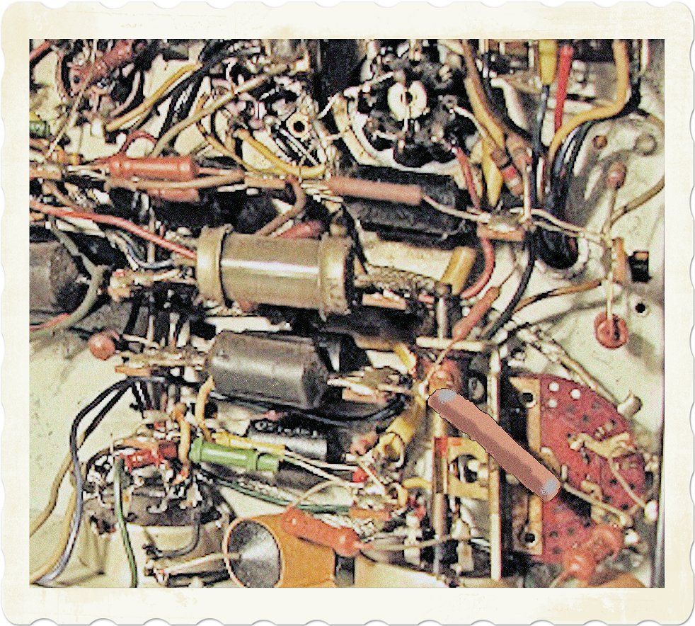
Bulky and messy circuit
well-organized printed circuit board
Working with printed wiring offers great advantages.
Printed wiring is designed based on a schematic taken directly from software on a computer. The probability of errors is therefore very much smaller. Printed wiring can be easily miniaturised, meaning that you can fit complex circuits into a very small space. Part placement can be automated by specially designed robots.
Printed wiring also comes with disadvantages, however, especially for the amateur. To design a PCB, you need to use software that is hard to master. Positioning, soldering, or replacing parts is precision work that requires special soldering equipment as well as very steady hands.
Lucky for you, if all that extra stuff seems like a major pain, there’s a ton of components with leads, experiment boards, and universal PCB’s just waiting for you to get hands-on. Check out Fritzing (https://fritzing.org/); it’s got an all kinds of ideas and projects to help you cook up some brilliant circuits with the aforementioned components and tools.
And guess what? Modern PCB-design is no longer just for pros; amateurs are getting in on the act, too. There’s all kinds of high-quality, open source (that means free!) software you can use to create schematics and print drawings (https://www.kicad.org/).
Oh, and did you know? Lots of companies will do the heavy lifting and handle the production process of the printed circuit board for amateurs — and not just for a fortune. These same companies often hook you up with tools for placing and soldering the components (https://www.eurocircuits.com/, for example). So, if you think you’re up for it, just hit up the ‘net and see where this journey takes you!
Rectifiers
With an alternating voltage/current, the electrons keep running back and forth. When we make circuits, they usually use a DC voltage between 3 V and 12 V. With a DC voltage/current, the electrons always run in one direction. If we have an alternating voltage source, we must first ensure that the electrons can only run in one direction. We convert the alternating voltage into a direct voltage and of course we do this with a diode. Below you will see various rectification diagrams with explanations.
Single-phase rectification
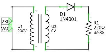
Above you see the schematic. A transformer turns 230 V alternating voltage into 9 V alternating voltage. With an alternating voltage, the current flows back and forth. If the current flows clockwise, the diode lets it pass. If the current wants to flow counterclockwise, the diode stops it.
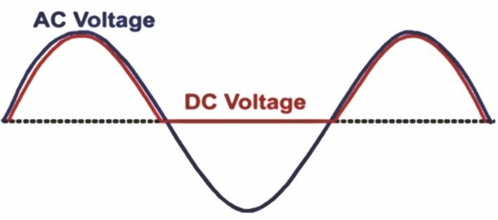
The graph shows the result of this circuit. The blue line is the voltage from the transformer. The red line is the DC voltage across the resistor. The first thing you notice is that the DC voltage becomes and remains zero when the AC voltage becomes negative. The diode then of course blocks the current through the resistor, no current through the resistor means no voltage across the resistor. Only the positive part (positive phase) of the alternating voltage is allowed through. That is why we call this single-phase rectification. If you look closely, you'll see something else that stands out. The DC voltage always remains a little lower than the AC voltage from the transformer. This is due to the forward loss voltage of the diode! As a result, not the entire alternating voltage falls across the resistor, but the voltage – FV. Most electronics will not work well on this DC voltage that keeps dropping out for a while!
Single-phase rectification with bucket capacitor
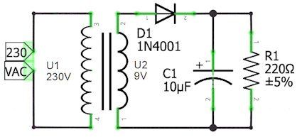
You see almost the same diagram here, except in this case a (bucket) capacitor has been placed after the diode. If the alternating voltage is positive, two currents now flow through the diode, the load current through the resistor R1, plus the charging current for the (bucket) capacitor C1. So the bucket capacitor is filled during the positive phase. If the alternating voltage is negative, the capacitor discharges (the bucket empties) via the load resistor R1. The smaller the resistance (the heavier the load) the faster the capacitor discharges.
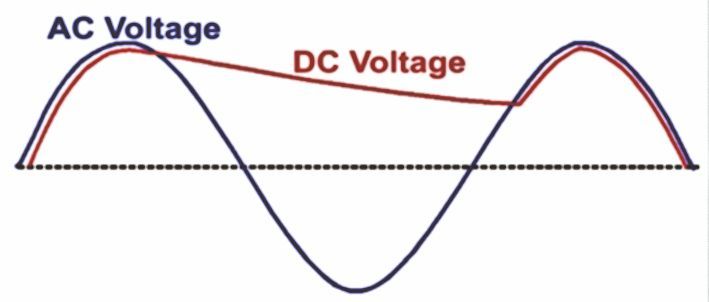
You can see in the graph above that the voltage in the negative part of the alternating voltage drops to less than 3 V. Also not an ideal situation if your circuit needs 5 V. What can help is a larger (bucket) capacitor, but the charging current will also increase considerably. So you must choose a source (transformer) and diode that can supply and pass that large charging current.
Full-wave rectification
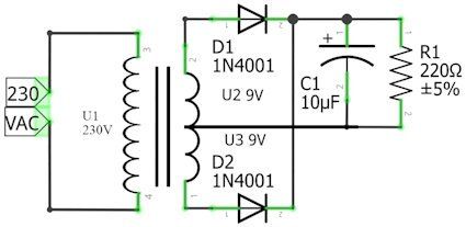
Rectification is of course much better if you could use both halves (phases) of the alternating voltage.
By far the most beautiful invention is therefore the solution of the full-wave rectifier. The transformer has a center tap on the output coil. The current is now sent through the load resistor using two diodes. When the current flows through the transformer to D1, it will pass the current to R1. The current returns via the center branch. D2 blocks (blocks) at that moment. If the current flows towards D2, it will pass the current to R1, while diode D1 is cut off. The (bucket) capacitor is therefore charged twice per wavelength instead of once. Therefore, the tension will also decrease less. The negative phase is thus made positive! Hence the name full-wave rectification.
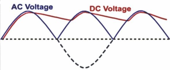
Diode bridge
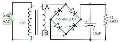
You need this circuit if the transformer does not have a center tap and you still want full-wave rectification. Two diodes are always on and two are off. Try it, how does the current flow if A is positive and B is negative? And if B is plus and A is minus? The result is almost the same as that of the previous circuit, but because the current always flows through two diodes, you are dealing with twice the forward voltage drop and double the power loss in the diodes.
AM-demodulator
A special single-phase rectifier is the AM demodulator. It consists of a diode followed by a capacitor.
This is the schematic of a real working radio receiver. So you can recreate it, if you want to!
Here’s how it works.
The coil, L1, and the adjustable capacitor, C1, together form a tuned circuit connected to an antenna. (See Resonance, page 147.)The AM modulated carrier wave is rectified via diode D1, then the high frequencies are filtered out, thanks to C2. The low frequencies that remain still have enough energy to directly drive a high-Ohm earplug.
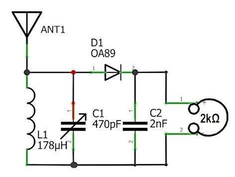
Relay
A relay is a switch that is electrically operated. A relay consists of a coil, an armature and two, or more, springloaded contacts. When we send current through the coil, it becomes a strong magnet. That magnet pulls the armature down. The other side of the armature then presses the spring-loaded contacts together; the switch is closed. When you turn off the current, the armature is no longer attracted by the coil. The spring-loaded contacts spring back and no longer make contact; the switch is open. The symbol for a relay consists of the symbol of a coil connected by a dotted line to one or more contacts. Read the entry about the coil, to better understand the following problem.
There is a problem if we want to switch off the relay. The coil wants to maintain the current but there is no circuit available to do so. The stored energy is then released as a voltage spike. When the coil is suddenly disconnected, this can lead to high energy pulses! In the case of a relay, this is something you don’t want, as it can destroy the electronics that are supposed to switch the relay. A free-wheeling diode solves this problem.

Basic relay symbol
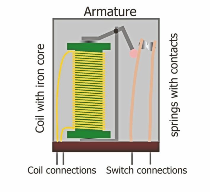
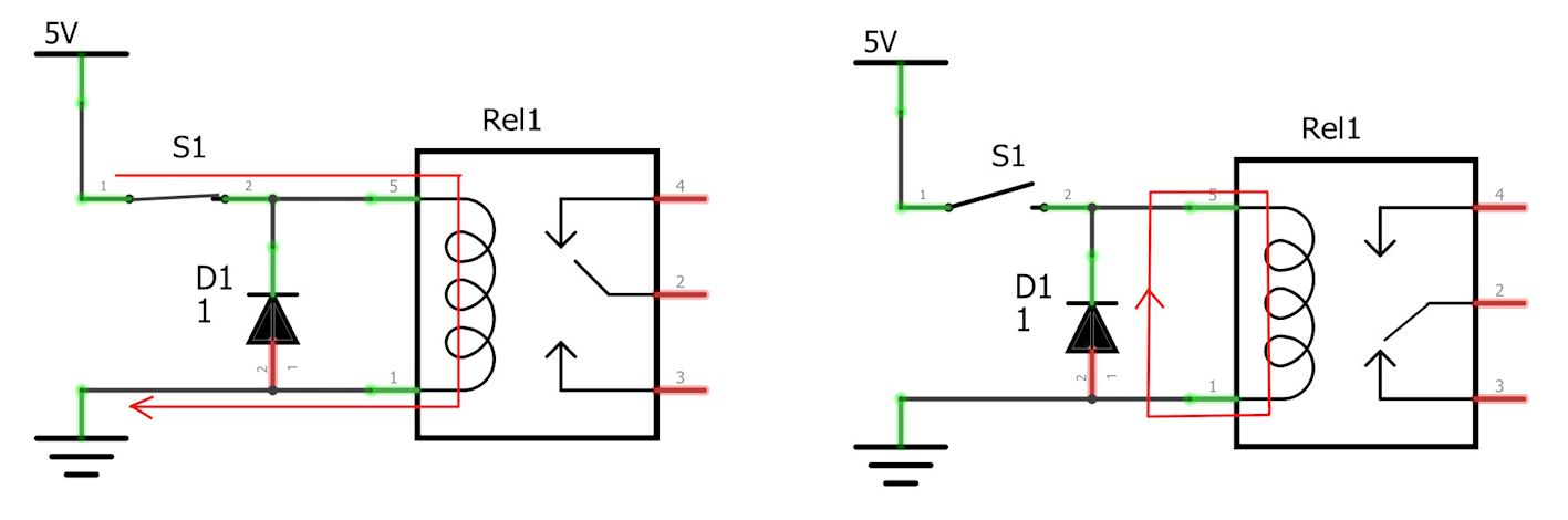
The free-wheeling diode
1 The relay is energized and a current flows through the coil from plus to minus. The diode is in reverse.
2. The relay is turned off. The current in the coil continues to flow for a while but is short-circuited through the diode, so there is no voltage spike.
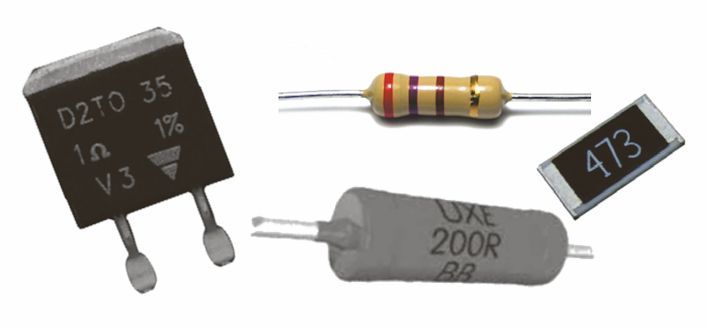
Different types of resistors
Resistor symbols
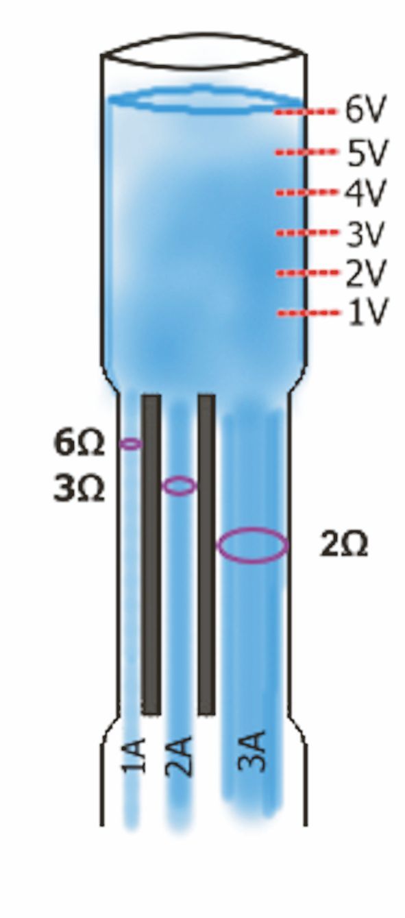
Resistor
As the word resistor suggests, resistors provide resistance to something. That something is a current. There are many different types of resistors. The resistor with leads, like those seen on the left in the picture, are still widely used, but on printed circuit boards a lot of SMC resistors (seen on the right in the picture) are now used, which are soldered directly to the board thanks to their metal edges. (for more information, see the entry on SMD or SMC).
In a schematic, resistors are represented by a rectangle with two connections, and their value next to it. In American and English schematics, the zigzag line is used with the value next to it. The unit of resistance is ohms, usually abbreviated to the Greek omega sign: Ω. A resistor has a value of 1 Ω if exactly 1 A of current flows when you put exactly 1 V of voltage across the resistor.
Water model of the resitor
If we use the water model and imagine our electrons as flowing water, a resistor can be compared to a thin tube. The thinner the tube, the less easily water can pass, the higher the resistance.
Ohm’s Law
Current will flow through the resistor only if a voltage is applied to the pins. The more voltage the more current will flow, but the greater the resistance, the less current will flow.
You can see this immediately in Ohm’s law:
A higher voltage means more current, a higher resistance means less current. Conversely, then, we know the voltage across a resistor if we know the current and resistance. And finally, we can calculate resistance if we know the voltage and the current.
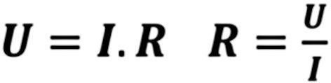
This applies to any resistor anywhere in a circuit!
Power
Resistors convert the voltage difference into power in the form of heat. A resistor gets hotter as the voltage increases, and also as the current increases. You can see this immediately in the formula for power
P.
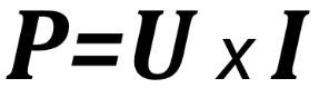
Where P is the power generated in Watts, U is the voltage across the resistor in Volts, and I is the current through the resistor in A.
The heat generated needs to be properly dissipated, otherwise the resistor will get too hot and may break down. Always make sure you use a resistor of the correct wattage, and have adequate cooling!
Tolerance
It is difficult to fabricate resistors with precise resistances. Manufacturers therefore specify how much the value of a resistor can vary (in percentage) from the specified value.
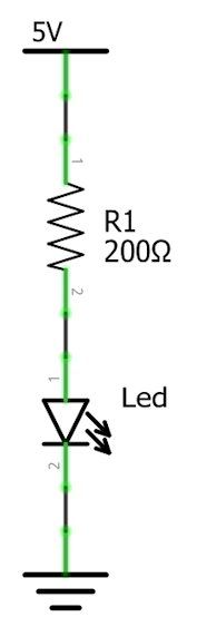
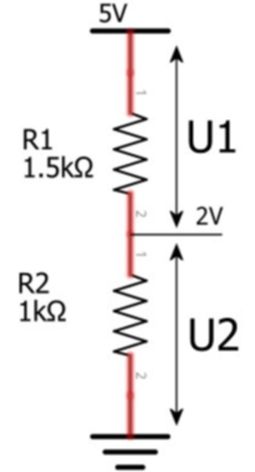
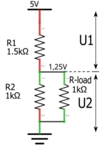
Basic applications of the resistor
Current limiting
Resistors often put in series with other components. Their main role? Limiting the current going through that component. A good example would be this LED controller. Suppose we want to light a LED at 5 volts. For instance, a LED with a “forward voltage” of 1 Volt. Once the voltage rises above 1 Volt the LED comes into conduction. This particular LED is at its best when the current running through it is 20 mA. Therefore, if we have current flowing through our LED, the voltage across the resistor is 4 volts (5V power supply minus 1 Volt Forward voltage drop). Now, we don’t want our LED to get more than 20 mA of current, so we need to calculate the resistance value. We can do this using Ohm’s law, which looks like this: R=U/I
By sticking to this law, we find that our needed resistance is: 4.0 ÷ 0.02, which equals 200 Ω.
Always remember to double-check the current limitation to keep things running smoothly!
Voltage divider
With resistors we can divide a voltage into several smaller voltages. Here you see a simple voltage divider. The input voltage is divided by the resistors into U1 and U2. You can calculate these with the following formulas:
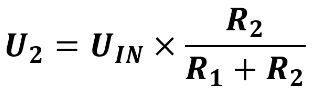
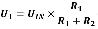
Things get a little more difficult if you want to connect a circuit to the voltage U2 that may/should operate at U2.That connected circuit of course also uses current and is in fact an extra resistor, also called a load resistor, or R-load for short. Before you can calculate the resulting voltages, you have to calculate the substitute resistor of R2 and R-load. To do so we use the “resistors in parallel” formula:
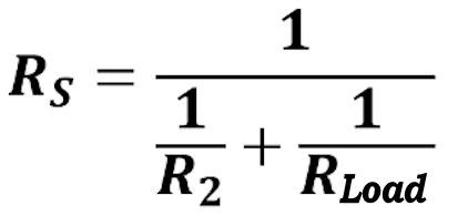
Once we have calculated the resistances in this manner, the formula for U2 is back to basic.
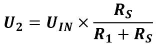
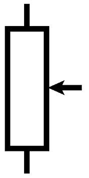
Potentiometer
A potentiometer is an adjustable voltage divider. It’s made from a big resistor with a sliding contact on top. This is easy to visualise if you look at the symbol - the slider is shown by a pointed arrow. When you crank the slider up, the lower resistance goes up and the upper resistance goes down, and the opposite happens if you slide it down.
Anti “floating” resistor
If a copper wire is not connected to anything, you never know what voltage is on it. Such a “floating” line is very sensitive to interference, so you certainly don’t want loose ends in your circuits. Yet you make that mistake easier than you think. Look at this very simple circuit of a single switch:
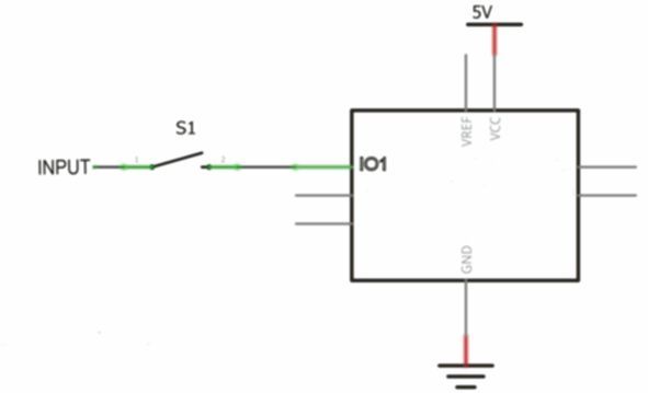
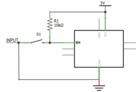
What’s the voltage at IO1 when the switch is open? The wire running from the switch to S1 is in a “floating” state, meaning it can take on any value! If there’s a surplus somewhere, electrons may just hop into the wire or induction voltages might crop up.
Obviously, we don’t want that!
So, we always ensure that a line is connected to something. How? By linking the line to a known voltage with a resistor, usually the supply voltage or zero. If we connect it to pull the voltage up, we refer to that resistor as a pull-up resistor. Conversely, if we pull the voltage down to zero, we call it a pull-down resistor.
When we use a pull-up resistor to define the open line, we can be sure about the voltage at IO1 when the switch is open - it’s 5V. However, when the switch closes, P drops to 0V.
Choosing the value of such a resistor is all about finding a balance. The resistor decreases the total resistance of the circuit, which in turn consumes energy. Take a 10 Ω resistor for example. It makes the input less affected by disturbances, but it demands a hefty 0.5 A, thereby consuming 2.5 watts when the switch is closed! A more typically used value for a 5V supply is 10 kΩ, and for a 3V supply, it’s 3.3 kΩ.
Make sure that all nodes in your circuit always have a defined state (or value).
Colour code for resistors.
Standard leaded resistors feature four rings. The ring that’s further apart from the others is known as the tolerance ring.
Ensure that it’s on the right. Each colour represents a value from 0 to 9:
black stands for 0, brown for 1, red for 2, orange for 3, yellow for 4, green for 5, blue for 6, purple for 7, grey for 8, and white for 9.
Starting from the left, note down the number each ring denotes. Your usual resistors have ring 1, ring 2, some number of zeros, then a tolerance. Therefore, by applying this colour code, the top standard resistor in the picture measures 470 Ω, with a tolerance of 2%. Precision resistors, like the bottom one in the image, carry an extra ring: ring 1, ring 2, ring 3, a bunch of zeros, and then comes the tolerance.
This means the precision resistor shown is 39000 Ω (also known as 39 kΩ) with a tolerance of 2%.
If there’s no tolerance ring (i.e., it’s blank), then the resistor’s tolerance is a broad ± 20%. Thus, such resistors can deviate considerably from the specified value, so it is better not to use them. For SMD/SMC resistors, there’s a written code consisting of usually three digits: the first two digits provide the value and the last one indicates the multiplier.(Read the entry on SMC/SMD for more info!)
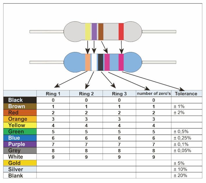
Resonance
When two waves meet, say at sea, a lot of things happen. Typically, the first wave may either boost the second wave slightly or reduce its intensity. But if the waves sync up perfectly, two unique instances occur. Imagine wave 1 is at the lowest point or in the valley, just as wave 2 hits its crest. The waves will essentially nullify each other; they vanish! However, a different scenario plays out if both the waves reach their peaks or drop to their valleys at the same time: They combine into a larger wave. This phenomenon results in the creation of gigantic 'monster waves' that dwarf all others around. If every wave at sea perfectly aligned, these monster waves would be a common sight. But in the chaotic realm of the sea, where waves crisscross randomly, it's rare for two waves to align flawlessly. Things are a tad different in electronics, though, where we have the ability to manipulate waves to line up precisely as we wish.
You know that we have two parts that allow us to shift a wave: the coil and the capacitor. With the coil, the current comes on slowly when we put a voltage across it. We call this post-cycling of the current. In the case of the capacitor, on the contrary, the voltage rises later when we send current through it; it is almost a short circuit at the beginning. The voltage is lagging behind the current.
So, the coil and the capacitor function in opposite ways. Therefore, when we connect a coil to a capacitor, the waves reach the junction with a delay. Often, these delays are inconsistent, resulting in varying waves; some are reduced in strength, and others are amplified. Only at a specific frequency do the delays align the waves perfectly in phase at the junction. We refer to this frequency as the resonant frequency. Then, at the junction, we can continually observe 'monster waves' at that frequency.
And this is the fundamental mechanism underpinning radios and televisions. Each channel is linked to a certain frequency. When you adjust your device to a specific channel, you are actually tuning it to resonate at the designated frequency. So, when you're turning the dial on your radio or choosing a channel on your TV, you're essentially creating the perfect conditions for these 'monster waves', allowing the reception and amplification of your selected broadcast.[Ian Hough1]
Of course, it is not the case that those waves just naturally arise there. If the circuit were lossless, then adding a charge once would be enough to make the waves flow back and forth forever. But of course there are losses. For instance, the copper wire of the coil has a small amount of resistance that converts some of the current into heat. So, you have to keep adding energy to the circuit to keep it going.
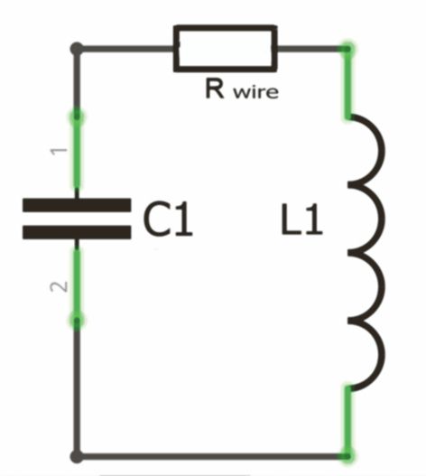
In the picture you can see such a circuit.
The uniqueness of this simple circuitry lies in its ability to amplify voltage at a certain frequency where the capacitor and the coil work in unison. At all other frequencies, either the capacitor (at higher frequencies) or the coil (at lower frequencies) takes precedence. At the resonant frequency, the circuit's AC resistance is significantly large, while on all other frequencies it's considerably smaller.
You understand then, that such a 'tuned' circuit is perfectly suited for receiving a radio wave of the exact resonant frequency. It severely weakens all other frequencies, yet at that one specific frequency, the signal undergoes no attenuation. Notice that in this configuration, the coil is parallel to the capacitor. There are also series circuits, where the coil is arranged in series with the capacitor. In these setups, the resistance at the resonance frequency is incredibly low, but much higher on all other frequencies.
Schematic and circuit
Imagine you're an animal trainer at the circus. Only your animals are billions of years old; they're electrons. And you can teach them to perform the most mind-blowing stunts! Forget jumping through a fiery ring, that's child's play compared to what electrons can do. How do we get them to do these tricks? We guide the electrons through mazes we've created in circuits. In these mazes, we set up all sorts of obstacles, slides, and tons of other electronic parts. However, it's hard to build a maze if you can't visualize it.
This is why we make a very precise drawing of each maze that we want to build. We call such a drawing a schematic.
Every part has its own unique symbol and all the connections are shown by lines. Moreover, each part in the diagram has its own number/letter combination, so you always know exactly which part you are talking about. You could draw a schematic on a paper, but it can get trickier when dealing with large circuits. However, with today's computer aided design (CAD) software, sketching a schematic and designing printed circuit wiring based on it, is a breeze! Guess what? There's also a free 'open source' CAD software that you can get your hands on. You can find it here: https://kicad-pcb.org/.
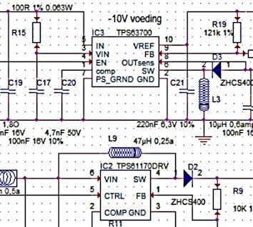
Serial and parallel
When you switch a number of electronic components in succession we refer to it as a series connection.
If you place a number of electronic components side by side, we speak of a parallel circuit
Resistors in series
The resistance of a number of resistors in series is equal to the sum of all resistances.

RSUB = R1+R2+R3
In the example above, RSUB is 3+8+5, which is 16 Ω (a good thing to remember: The result is always greater than the largest resistance of the series)
Resistors in parallel
When you connect resistors side by side, the total resistance becomes smaller and smaller.
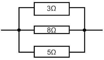
You can calculate the total resistance using the following formula:
1/R-total = 1/R1+1/R2+1/R3 and so on. In our example, R-total is 2.6 Ω. It's helpful to note that the total resistance is always lower than the smallest resistance in the circuit.
The connecting wires, represented by the black lines, have 0 Ω resistance. In the diagrams, I've illustrated the highest resistance as the narrowest tube. However, in genuine electronics schematics, the rectangles are all uniform in size, with their values inscribed next to or within them.

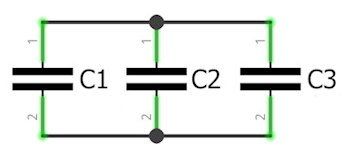
Series and parallel connection of capacitors
For capacitors, the two above calculations are reversed.
Condensator in series
When you connect capacitors in series, the capacitance becomes smaller and smaller and the AC resistance becomes larger and larger.
The replacement value consists of the addition of the inverse values:
1/CSUB = 1/C1+1/C2+1/C3 and so on.
Capacitors in parallel
Connecting capacitors in parallel results in an increase in capacitance. This is due to the AC voltage across all capacitors being identical, and the plate area expanding each time an additional capacitor is parallelly connected.
For the equivalent capacitance C, derived from capacitors C1 through Cn connected in parallel, we simply sum up the capacitance of each individual capacitor.
CSUB = C1+C2+C3, and so forth.
Series and parallel connection of coils
Calculating with coils is not as easy as with resistors and capacitors. Coils are sensitive to magnetic fields, but they also create them themselves when you send current through them! So, if you place coils in series or in parallel, they will always interact with each other's magnetic field. Therefore, there are no simple calculation rules that can be given for coils in series and parallel; they’re too complicated for that.
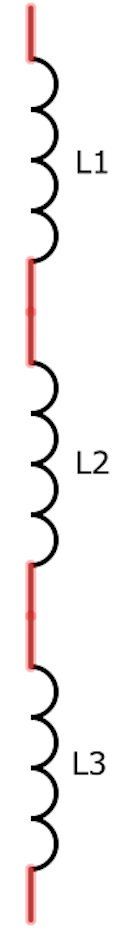
Coils in series
if we leave that out of consideration, you could use the following formula for coils in series:
LSUB = L1+L2+L3
R more generally LSUB = L1+ L2…..+Ln (where Ln is the last coil.)
The DC resistance of the coils adds up too!
Coils in parallel
With coils in parallel is even harder to predict a substitution value.
If the distance between the coils s is so wide that no magnetic coupling could occur, you could use the following formula:
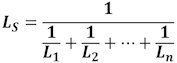
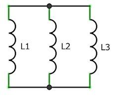
However, coils will almost always suffer from magnetic coupling. If the coils are completely in each other’s magnetic field, the coupling is complete. If the direction of their fields is the same, the parallel connection will not affect the self-inductance. The direct current resistance, of course, does decrease.
If the direction of their fields is opposite, they cancel each other’s self-induction! If they are also of different values in the process, currents start flowing between them, which can make them hot and might even cause them to break down.
SMC of SMD
The parts I used back in my day were often large and bulky. These days, the components on a printed circuit board, or PCB, are super small. They're soldered directly onto the PCB's surface, which is why they're called "surface mounted components" (SMC) or sometimes "surface mounted devices” (SMD).
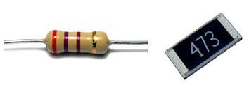

Fortunately, parts with leads still exist.
It makes it very easy for us inventors to quickly cobble something together on an experiment board. “Huh, an experiment board?”, you might be wondering, “What the heck is that?” Well, experiment boards are made especially for tinkerers like you and me. These are thick plastic plates with holes, under which there are copper springs. Those springs are connected in rows, so that you can quickly put a circuit together. Using it’s official name, we would call it a breadboard, and you are definitely going to need one if you want to experiment. Fortunately, they are not expensive.
The picture shows a breadboard that has 2 x 20 rows, each with 5 connected holes.
On either side, there are two power-lines, broken up into groups of 5. As illustrated in the top part of the image, the connection pattern of the copper springs is indicated by coloured lines:
Every row has five points: a, b, c, d, and e, which are linked together. The same goes for points f, g, h, i, and j. The power-lines are drawn in red and blue colours, showing that every 5 holes in a vertical line are connected.
As an example: The red wire on the left hooks up with the resistor through the positive (+) supply pins. The other end of the resistor is linked to the LED's anode in row 8. The second lead of the LED (cathode) plugs into row 10. That row 10 then connects to the negative (-) supply pins with a blue wire. So, when you attach a battery to the red and blue wires, voila, the LED lights up.
Fritzing (www.fritzing.org) provides an on-line tool to draw schematics and the corresponding wiring diagram for on an experiment board.
Solar cell
You already know that you can use electricity to make light. But it is also possible to convert light energy back into electrical energy. And we have an inexhaustible source of such energy in the sky: the sun. There are many ways to use solar energy; the solar cell is a way to convert solar energy into electrical energy. Solar cells are made so that striking sunlight creates a voltage on the terminals of the solar cell. Unfortunately, they aren’t very efficient. At best, of 20% of the striking light will be converted into electricity (at present). Encouragingly, however, a lot of people are working on that. One invention after another is making sure that the efficiency of solar cells is gradually improving. Exactly how a solar cell works is so complicated that the famous scholar Albert Einstein had to be brought in to explain it. For us, it is enough for now that we know it works. Even if your house doesn’t have big solar panels, you may have encountered solar cells if you have a garden. Cheap garden lights all contain solar cells. These lights rust quickly and then have to be replaced after only a year. A shame for the environment, but nice for us: the solar cells are usually still fine to use! The cells have two terminals on which a direct voltage is produced when you hold them in the sun. Fun fact: If you were to use light from a lamp, the solar cell will work from that as well. (Thus you can use them as a light sensor as well)
Solar cells, however, can only generate a little power. Their maximum voltage is 0.6V volts and the maximum current is about 3 amperes, making their maximum power 1.8 watts. This presents us with a problem: Virtually no electronic component works at 0.6 volts. That is why the cells are assembled together in a solar panel. Connecting them serially increases the supplied voltage. Connecting them in parallel produces more current. You can make your own solar panel by putting several cells together.
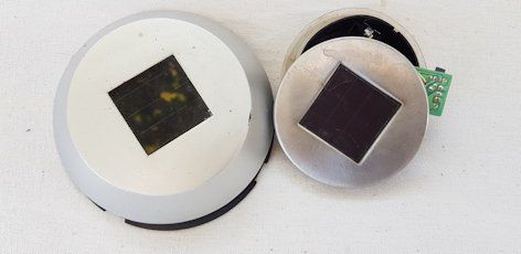
“Old” garden lights with solar cells.
Soldering
Metals become liquid if you heat them enough They do not all have the same melting point. Copper melts at a temperature of 1080 °C, while silver melts at 960 °C, and tin at 230 °C. When you mix metals, a process known as alloying, the resulting alloy doesn't have a specific melting point. Instead, it first turns viscous, then progressively more fluid as it gets hotter. If this liquid alloy comes into contact with another metal with a higher melting point, an alloy forms at the interface. Leaving the metals to cool undisturbed, results in a mechanical and electrical bond, a process utilized when attaching parts together or to a circuit board, known as soldering.
Today we use a mixture of tin and silver as solder. This solder can be melted using a soldering iron - a tool with a heated tip made of a metal with a high melting point, so it remains solid while melting other metals.
Tin/silver solder works well at about 380°C. Unfortunately, your soldering tip also loses atoms to the hot liquid, so it is slowly "eaten".
Another challenge is that liquid metal can readily bond with oxygen in the air, resulting in the metal becoming oxidized. Metal oxides are very poor conductors for both electricity and heat, making them unsuitable for our purpose. For this reason, an antioxidant, known as flux, is incorporated into the solder to prevent oxidation. Today, this agent is already included in the solder wire.
It would probably be helpful to look at an online soldering course or demonstration. That way, you'll quickly figure out how to do it. For instance: https://www.vse.com/blog/2022/05/10/through-hole-soldering-a-guide-to-the-best-practices/
Key techniques like ensuring the solder flows well and avoiding the use of excessive solder are crucial.
Beware, solder fumes are toxic, so make sure you have good ventilation or - better yet - a good extractor.
Switches
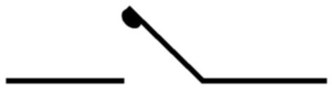
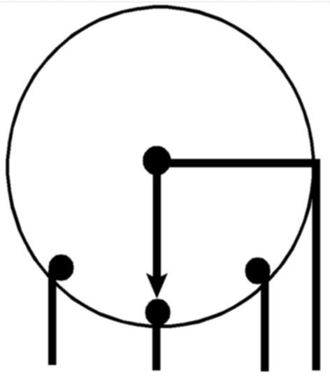

Usually, you want to be able to turn the power supplying a circuit on and off. For example, you don't want to always leave the lamp in your room on. Fortunately, there is a switch in the wall that lets you turn the lamp on or off.
A switch typically has two parts made of conductor material, similar to the switch in circuit 1. When these conductors meet, they create a connection, closing the circuit. These conductive pieces are referred to as contacts. Essentially, a switch has contacts that can be opened or closed. When the contacts are in their closed position, the switch connects the wires it is attached to, whereas it disconnects them when the contacts are open.
There are numerous types of switches. Some switches can be rotated and usually offer multiple positions. These typically have one or more poles that connect to different contacts with each rotational click. These are known as rotary switches.
For high currents and voltages, there are switches that are filled with nitrogen, or contain a vacuum where the air has been sucked out. That way, the contacts cannot spark or burn.
Small switches are frequently used on the printed circuit board, or PCB for short. These can be changeover switches that remain in the position you set. Additionally, momentary switches like push buttons are commonly utilized.
A momentary switch only makes or breaks contact when you press it. As soon as you release, the switch springs back to its normal setting.
Transformer
A transformer is used to reduce an alternating voltage. A transformer is comprised of two distinct but tightly intertwined coils. The symbol for a transformer is like two coils laid flat next to each other, usually with a couple of lines between them. These lines tell us there's a core made of soft iron inside. The symbol isn't always the same though, because transformers can be different from one another.
Why do different transformers have more or fewer windings? A winding is exactly one wire loop of a coil. By changing the number of windings, we change the voltage and maximum current of the transformer coils. If we do not take losses into account, the power output of one coil is equal to the power input of the other.
Imagine one side of a transformer has a coil with lots of thin windings, and the other side has only a few thick windings. This is the case for mains transformers, which are designed to shrink down the 230VAC voltage from our wall outlet. These handy transformers, like the example transformer below, come as standard, with output voltages starting from 3V. Depending on the number and thickness of the windings in the coil, they can supply various amounts of voltages and currents. This means we can easily snag some low AC voltage for our needs.
Look at this picture of a transformer. It has three output voltages (6 V, 9 V, 12 V) and it can deliver 0.5 A at 12 V. You can also use the 6V, 9V and 12V tap as a two times 3Volt supply with mid-tap. If we take the power output and power input, for convenience, to be equal, 12V 0.5 amps requires only 20 milliamps at the 230VAC input.
Tip: A transformer also works the other way around, so you can turn a low voltage into a high voltage.
Transistor and MOSFET
`If you make the valve of a diode adjustable, you get to decide how much current goes through the diode.
This type of component has three connections: two that carry the main current, and one to command the current. You've got a choice in terms of how you want to manage the main current: it can be done by current control, or by using voltage control. With the first choice, we're talking about a bipolar transistor, also known as a BJT. For the second choice, we call that a MOSFET.
Both have their advantages and disadvantages, but both are great at managing a large amount of current.
See the symbols opposite.
Transistors come with three connections: the collector, emitter, and base. The base is like the controller, where a little current manipulates the big current flowing between the collector and emitter. In an NPN transistor, the emitter spits out the large current while the collector takes it in. But in a PNP transistor, it is the opposite. You can easily spot whether an emitter is NPN or PNP by looking at the direction of the emitter's arrow.
Now, in MOSFETs, the three connections are named differently: they're called the drain, gate, and source. You can match these up to collector, base, and emitter. In the N-channel version, current rushes from the drain to the source. However, in the P-channel version, the current zips in the opposite direction, going from source to drain.
Remember: the transistor is current-controlled, the MOSFET is voltage-controlled.
De NPN transistor
Let's go back to the water model to visualize how electricity flows. Picture an NPN transistor like this: a rubber patch full of holes laid on a metal plate. The plate has holes too, but when the rubber patch is on the plate, the holes perfectly cover each other. Now, imagine if I stream water between the plate and the rubber patch through a side pipe, the patch will get lifted off the plate, and the holes will be uncovered. Voila, we have flow!
The more water I pump from the side, the bigger the gap between the patch and the plate, and the more current will flow. At some point, the patch and plate are so distant that the maximum current is rolling; adding more water from the side won’t do anything. If we take the water model further, there’d be a one-way valve at the transistor’s bottom, just like in a diode, so that the water can't flow back. Since a transistor is like a tuneable diode, it also has a forward voltage drop between the base and the emitter. This voltage drop can be anywhere from 0.5 to 0.9 V. In our calculations, we'll stick to 0.7V.
So, the transistor is basically a big diode tube that you can open up by using current. You send current into the big tube by using a small diode tube. The collector is the input of the big tube. The emitter is the output of the big tube. In formula terms it is like this:

How far the large tube opens due to the small auxiliary current through the base is different for each type of transistor. We call this the current gain factor, and the symbol is ß. Multiplying the base current by the current gain gives you the corresponding collector current. As a formula it looks like this:

With the help of these three straightforward formulas, you can figure out the right resistors for each circuit to make the transistor work just the way you want.
When a transistor is fully 'switched on' ( in saturation), it maintains a forward loss voltage—ranging from 0.2 V to about 0.5 V— between the collector and emitter. At high currents, a transistor can get quite warm, and even hotter if it's only half opened. That's why we usually see transistors being cooled.
The specifics of a transistor are listed in a data sheet provided by its manufacturer. Here, you'll spot details like the max voltage between the collector and emitter, the max current, the max power, and the transistor's gain factor. Sometimes, you'll also see the highest frequency the transistor still functions at.
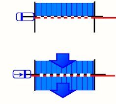
The N-MOSFET works slightly differently:
Translated to water model terms again. Here, two gratings lie on top of each other, exactly so that they close off each other's holes and no water can flow. If I now exert pressure from the side on the upper grid, it slides to the side and the holes are exposed. The further I slide the grid, the more water can flow. Once the holes are exactly on top of each other, the maximum flow has been reached. If I stop applying pressure, the top plate springs back, and the flow is shut off. With a MOSFET, much like with a transistor, the current cannot flow backwards.
The MOSFET needs a minimum pressure to slide the valve open. This voltage varies greatly. Therefore, MOSFETs have their own minimum gate voltage (VGS). This is the minimum voltage it requires to open up. Keep in mind, this could be 10 V or maybe even more. Calculation-wise, a MOSFET is a bit trickier, but since we're only using it as a switch right now, we don't need to crunch those numbers. If the gate voltage is significantly higher than the VGS, the MOSFET will fully open. A tiny internal resistance remains, usually just a few to tens of mΩ in most MOSFETs. Because of this low resistance, MOSFETs are great choices for controlling large currents, as the forward loss voltage and power loss are incredibly small.
As an example, a MOSFET with an ON resistance of 12 mΩ has a voltage drop of 10x0.012 = 0.12 V at 10 A so a power of 1.2 Watts. A transistor with 0.3 V loss there would produce as much as 3 Watts of heat.
Again, you can find all the important data about MOSFETs on the data sheet.
By now it is probably clear that most components have all manner of variations. This also applies to the BJT and the MOSFET. Fortunately, there are many transistors and MOSFETs that are pretty much universal, and those are the most commonly used.
Transistors and MOSFETs play an important role in electronics; almost everything uses them in some way. You can use them as switches, memory elements, amplifiers, and much more. In the BIY circuits of the book, you'll encounter a number of practical applications for these components.
Basic transistor circuits
There are three basic schemes for transistors. The most common is the common emitter topology.
The common emitter circuit
Here you see an ordinary NPN transistor in conduction. There are 2 circuits: the base-emitter circuit (red arrows) and the collector-emitter circuit (purple arrows).
The base receives current through Rbase. Ohm's law applies to R1, so the current through R1 (and the base) is equal to 4.3/47000 = 0.09 mA. The base voltage is 0.7V remember?
The collector current is then ßX0.09 mA = 200x0.09 mA = 18 mA. The emitter current is then, of course, 18+0.09 = 18.09 mA. Across the collector resistor is 0.018*220 = 3.96 V (law of Ω U = I*R). The power supply pushes the current through the circuits so the current flows through the power supply from 0 to +5 V.
This little circuit can be used for lots of fun inventions.
Since the emitter is at zero, so it is used for both input and output, hence the name: 'common emitter circuit'.
Here's a look at the PNP transistor in a common emitter circuit. You might find it takes some getting used to, but as you'll notice, the transistor does everything the same as the NPN transistor, just flipped. The emitter is directly connected to the 5 V line. This 5 V line now serves as the mutual line for both input and output. The base always sits at 0.7 V lower than the emitter, so the currents go in opposite directions. You'll start seeing how mixing NPN and PNP opens up a heap of possibilities.
The supply line is effectively a zero for all signals. This is because the power supply makes sure the supply voltage stays steady (5 V in our example). If an AC voltage signal arrives at the supply line, it gets routed to ground through the power supply.
If you apply an alternating current variation to the input of a CES (the base), it will appear in reverse at the output (the collector). So the GES is an inverter!
Universal PCB
If you've made a good, working circuit on your experiment board, you'd probably want to use it elsewhere. But the big, clumsy bread board is not very handy. If you’ve got a small circuit figured out, a piece of universal board is your friend. This is a printed circuit board with rows of through-hole pads only. You poke the leads of the components through these pads and solder them in place. Finally, use wires to connect the soldered components.
The image presents the circuit dubbed “the lightning machine,” assembled on a universal board. On the left, you’ll see the topside showcasing the components and heat-sink. The bonds on the underside are faintly visible, along with the pads. The right side reveals the bottom of the assembly board, where all connections are clearly seen. The red dots mark where a lead from a component pokes through a hole. So, those tiny pads are soldered. You can also purchase various mounting boards that feature interconnected pads arranged in rows or groups, and there are unique models designed specifically for microcontroller boards.
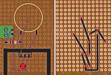
Waves
In the world of electronics, waves play a substantial role.
Light? It's made up of electromagnetic waves (check out the article on electromagnetic waves for more info).
Sound? It travels in the form of a wave.
And alternating current? Yep, you guessed it, it also comprises waves.
To gain some insight into waves, we can picture waves on water as our model. Most of the time, these water waves aren't travelling solo. They're actually a mix of several waves. But, if you squint, you can usually discern a pattern.
So what causes these waves in the water? Typically, currents or wind take the blame. If there's no current or wind, the surface will be still and smooth. You could compare this state to equilibrium. Should the water start to ripple, then it's moving around this equilibrium point. Within this movement, you'll find a wave crest, riding above the surface, and a wave valley, ducking just below.
Let's consider a hypothetical scenario where all disturbances and noise are erased. In that case, the wave may look something like this. This waveform is called a sinus. I use the sinus waveform do explain the properties of a wave.
The red line shows where the water is when at rest. You can see that the wave crests fit exactly into the wave valleys. They are actually the same height, but inverted. The height of a wave crest (or the depth of a wave valley) is what we call the amplitude. The higher (and therefore also lower) the wave, the greater the amplitude. Both crest and valley height together is called peak-to-peak amplitude.
The green lines show exactly one wave; it represents the “flow” of the wave from start to finish: Up to the peak, back down to equilibrium and then continuing all the way down to the valley, then back up to the equilibrium. After that, a new wave begins and the cycle repeats. The distance between the green lines is very appropriately called wavelength.
And with that you know all the properties of a wave, the amplitude A and the wavelength ʎ.
You're aware of waves that progress and travel, like the waves you see in the ocean. But, did you know there is another type called a standing wave, too? These waves are quite unique. With these, you can see the wave valley and the wave crest swapping places in a regular rhythm, right in the same spot every time.
This swapping rhythm—how many times per second they switch—is known as the frequency, denoted by the symbol 'f.'
Now, if we deal with a wave that's on the move, it gets even more interesting. As you watch, the wave whizzes by, the speedier the wave moves, the quicker you observe the wave peaks and valleys flitting past you.
This means the frequency—which is essentially how many times the wave bobs up and down each second—goes up when the wave picks up speed.
This involves the following formula:
Where
 in f is the frequency , V is the speed at which the wave is moving and ʎ is the wavelength. Compare it to a comb that you run along your nail. The faster you move the comb the faster the teeth tap against your nail; the frequency increases. The further apart the teeth are, the lower the frequency is. So speed up, frequency up. Slow down (or make the wavelength longer), frequency down.
There are also a lot of waves that are not very nicely sinusoidal at all.
As long as they are nicely equal (symmetrical) everything fits together well. If they are unequal, for example a sudden wave peak or valley on its own (pulse) now and then, the above rules do not longer apply. For clarity I added an illustration with some of these irregular waveforms.
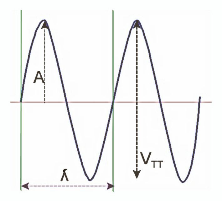
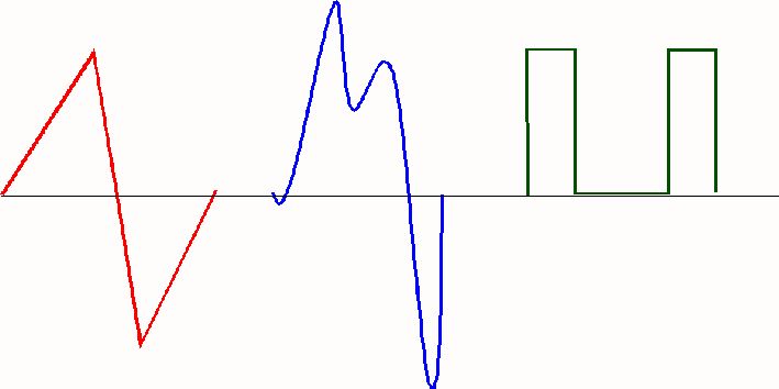
Datasheet 1N5401G
1N5401G is a diode.
It looks like the bottom part of the illustration.
The cathode is at the side with the ring.
Maximum reverse voltage = 100 V
Maximum current = 3 A
Forward voltage loss FV = 1 V
Leakage current = 5 µA
This diode is part of a series 5402, 5404, 5406
The last number is an indicator for the maximum reverse voltage:
1 = 100 V, 2 = 200 V etc.
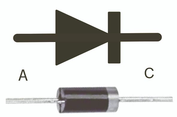
Datasheet HLMP-1700
The HLMP-1700 is a LED that already gives very good light at 5 mA.
The forward loss voltage is then about 1.7 V. The LED is available in red, yellow, and green. The head is 3mm thick.
The HLMP 4700 is quite similar but has a 5mm head
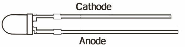
Datasheet BC550C
The BC550C is a NPN transistor.
See the illustration for the connections.
Maximum supply voltage = 45 VMaximum collector current = 100 mA
Maximum power = 0,625 Watts
Current gain ß (hfe) = 270-500
The last character of the type-number
stands for the ß, A is the lowest ß, D the highest.
There are a lot of compatible transistors available,
with only a different maximum voltage.
BC546 / 65V, BC547 / 45V, BC548 / 30V. BC549 / 30V and BC550 / 45V.
S0, they can all be used for the circuits in this book.
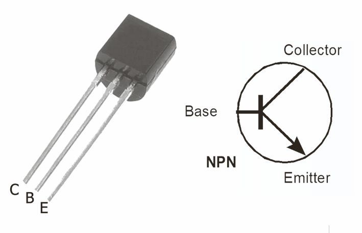
Datasheet BC559B
BC559B is a PNP transistor.
See the illustration for the connections
Maximum supply voltage = 30 V
Maximum collector current = 100 mAMaximum power – 0,5 Watts
Current gain ß (hfe) = 200-450
The last character of the type-number
stands for the ß, A is the lowest ß, D the highest.
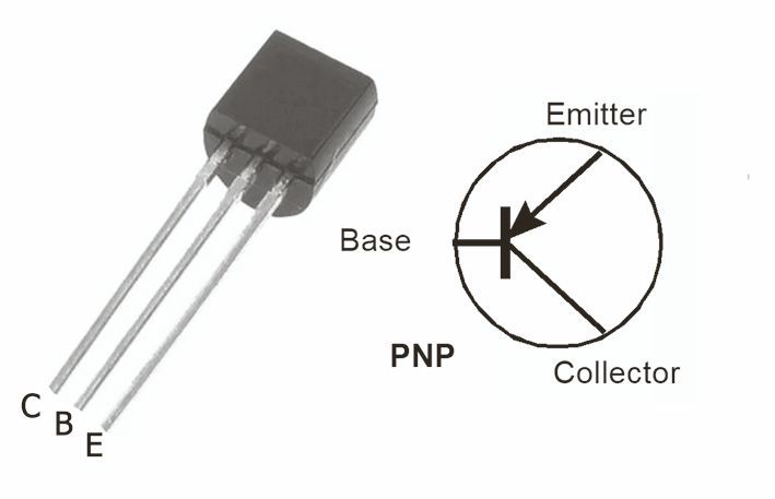
Datasheet KSD880Y
KSD880Y is a NPN power transistor.
See the illustration for the connections.Maximum supply voltage = 60 V
Maximum collector current = 3 A
Maximum power 30 Watts
Current gain ß = 60 - 300.
If you want to control power with this transistor
be sure to mount an adequate heatsink
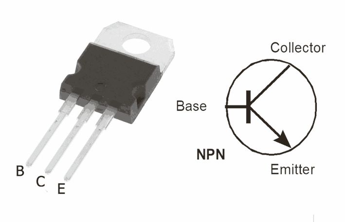
Datasheet AGQ20T03
The AGQ20T03 is a relay for small currents.
The connections are shown in the picture, The pictures are drawn from a top-down view. Contacts 3 and 6 are the parent contacts. By default, they are connected to the Normally Closed contacts: 2 to 3 and 6 to 7. When the relay is turned on, 3 and 6 are correctly connected to the Normally Open contacts: 2 to 4 and 6 to 5.coil voltage is = 3 V DC
coil current =33 mA
coil power consumption = 100 mW
maximum contacts voltage = 30V
maximum contacts current = 2 A.
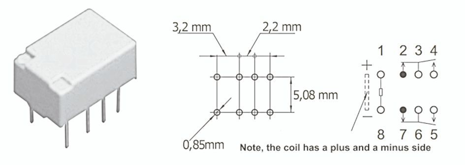
Datasheet NSL-19M51
The NSL-19M51 is a light-dependent resistor sensitive to visible light.
Because it is a resistor it has only two leads and no polarity.
The resistance ranges from 20 MΩ in darkness to at least 5 kΩ in full daylight.
Maximum Voltage ACor DC = 100V
Maximum power dissipation = 250 mW